Remote Support and New York Installs. Need a Service? Call us at (718) 500-4114.
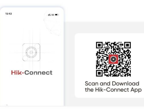
Hik-Connect iOS Mobile Client
User Manual

Legal Information
©2022 Hangzhou Hikvision Digital Technology Co., Ltd. All rights reserved.
The Manual includes instructions for using and managing the Product. Pictures, charts, images and all other information hereinafter are for description and explanation only. The information contained in the Manual is subject to change, without notice, due to firmware updates or other reasons. Please find the latest version of this Manual at the Hikvision website ( https:// www.hikvision.com/ ).
Please use this Manual with the guidance and assistance of professionals trained in supporting the Product.
![]() and other Hikvision’s trademarks and logos are the properties of Hikvision in various jurisdictions.
and other Hikvision’s trademarks and logos are the properties of Hikvision in various jurisdictions.
Other trademarks and logos mentioned are the properties of their respective owners.
TO THE MAXIMUM EXTENT PERMITTED BY APPLICABLE LAW, THIS MANUAL AND THE PRODUCT DESCRIBED, WITH ITS HARDWARE, SOFTWARE AND FIRMWARE, ARE PROVIDED “AS IS” AND “WITH ALL FAULTS AND ERRORS”. HIKVISION MAKES NO WARRANTIES, EXPRESS OR IMPLIED, INCLUDING WITHOUT LIMITATION, MERCHANTABILITY, SATISFACTORY QUALITY, OR FITNESS FOR A PARTICULAR PURPOSE. THE USE OF THE PRODUCT BY YOU IS AT YOUR OWN RISK. IN NO EVENT WILL HIKVISION BE LIABLE TO YOU FOR ANY SPECIAL, CONSEQUENTIAL, INCIDENTAL, OR INDIRECT DAMAGES, INCLUDING, AMONG OTHERS, DAMAGES FOR LOSS OF BUSINESS PROFITS, BUSINESS INTERRUPTION, OR LOSS OF DATA, CORRUPTION OF SYSTEMS, OR LOSS OF DOCUMENTATION, WHETHER BASED ON BREACH OF CONTRACT, TORT (INCLUDING NEGLIGENCE), PRODUCT LIABILITY, OR OTHERWISE, IN CONNECTION WITH THE USE OF THE PRODUCT, EVEN IF HIKVISION HAS BEEN ADVISED OF THE POSSIBILITY OF SUCH DAMAGES OR LOSS.
YOU ACKNOWLEDGE THAT THE NATURE OF THE INTERNET PROVIDES FOR INHERENT SECURITY RISKS, AND HIKVISION SHALL NOT TAKE ANY RESPONSIBILITIES FOR ABNORMAL OPERATION, PRIVACY LEAKAGE OR OTHER DAMAGES RESULTING FROM CYBER-ATTACK, HACKER ATTACK, VIRUS INFECTION, OR OTHER INTERNET SECURITY RISKS; HOWEVER, HIKVISION WILL PROVIDE TIMELY TECHNICAL SUPPORT IF REQUIRED.
YOU AGREE TO USE THIS PRODUCT IN COMPLIANCE WITH ALL APPLICABLE LAWS, AND YOU ARE SOLELY RESPONSIBLE FOR ENSURING THAT YOUR USE CONFORMS TO THE APPLICABLE LAW. ESPECIALLY, YOU ARE RESPONSIBLE, FOR USING THIS PRODUCT IN A MANNER THAT DOES NOT INFRINGE ON THE RIGHTS OF THIRD PARTIES, INCLUDING WITHOUT LIMITATION, RIGHTS OF PUBLICITY, INTELLECTUAL PROPERTY RIGHTS, OR DATA PROTECTION AND OTHER PRIVACY RIGHTS. YOU SHALL NOT USE THIS PRODUCT FOR ANY PROHIBITED END-USES, INCLUDING THE
DEVELOPMENT OR PRODUCTION OF WEAPONS OF MASS DESTRUCTION, THE DEVELOPMENT OR PRODUCTION OF CHEMICAL OR BIOLOGICAL WEAPONS, ANY ACTIVITIES IN THE CONTEXT RELATED TO ANY NUCLEAR EXPLOSIVE OR UNSAFE NUCLEAR FUEL-CYCLE, OR IN SUPPORT OF HUMAN RIGHTS ABUSES.
IN THE EVENT OF ANY CONFLICTS BETWEEN THIS MANUAL AND THE APPLICABLE LAW, THE LATTER PREVAILS.
Symbol Conventions
The symbols that may be found in this document are defined as follows.
|
Symbol |
Description |
|
|
Indicates a hazardous situation which, if not avoided, will or could result in death or serious injury. |
|
|
Indicates a potentially hazardous situation which, if not avoided, could result in equipment damage, data loss, performance degradation, or unexpected results. |
|
|
Provides additional information to emphasize or supplement important points of the main text. |
Contents
Chapter 5 Video & Cloud Storage 45
Chapter 6 Camera / NVR / DVR 63
Chapter 9 Panic Alarm Device 143
Chapter 13 Other Functions 157
Chapter 14 System Settings 158
Chapter 1 Overview
Hik-Connect iOS Mobile Client runs on phones and tablets with iOS 10 or later. With the Mobile Client, you can remotely control devices (NVRs, DVRs, network cameras, indoor stations, doorbells, security control panels, access control devices, etc) via Wi-Fi or cellular network. You can also share your devices to other accounts and use devices shared from other users.
![]()
Note
The Mobile Client provides access to the Hik-Connect service, which is a cloud service developed by Hikvision, to manage your devices.
Network traffic charges may be incurred during the use of the Mobile Client. Consult your local carriers for details.
![]()
-
-
System Requirements and Conventions
iOS 10.0 or later.
In the following chapters, this manual simplifies Hik-Connect Mobile Client as “Mobile Client”, device such as DVR, NVR, encoder, and network camera as “device”, and device which supports being added to Hik-Connect service as “Hik-Connect Device”.
-
Summary of Changes
-
See detailed descriptions on feature changes on the Mobile Client in Hik-Connect Mobile Client Release Notes .
Chapter 2 Account
You need a Hik-Connect account to manage your devices online, use the cloud features, and share devices with others. You can use the visitor mode to experience the app with a temporary account and register an account of your own later.
-
-
Select Region at First Time Running

Note
The first time you run the Mobile Client, you should select the region where your devices are located. Otherwise, the live view, playback and alarm notification of the devices will fail.
You should select the region where your devices are located, or subsequent operations may be affected.

After running the Mobile Client, tap Select Region to select a region.
-
Registration
Note
You can register an account by your mobile phone number or your email address. With a registered account, you can log in to the Mobile Clients running on different mobile phones, which provides convenience for managing your devices.
You can use visitor mode to manage your devices without registration. See Visitor Mode for details.

-
You can register an account by your email address.
-
Tap Login/Register on the Home page.
-
Tap Register to enter the Join Us page.
-
Tap Terms of Service and Privacy Policy to read the relevant content and then tap Agree to continue.
-
Select the region where your devices locate.
-
In the Register page, enter your email address and then create a password.

Note
We highly recommend you to create a strong password of your own choosing (using a minimum of 8 characters, including at least three kinds of following categories: upper case letters, lower case letters, numbers, and special characters) in order to increase the security of your product. And we recommend you change your password regularly, especially in the high security system, changing the password monthly or weekly can better protect your product.

-
Tap Get Security Code to get the security code for verification.
-
Enter the security code you received, and then tap Finish.
-
-
Register by Mobile Phone Number
You can register an account by your mobile phone number.
-
Tap Login/Register on the Home page.
-
Tap Register to enter the Join Us page.
-
Tap Terms of Service and Privacy Policy to read the relevant content and then tap Agree to continue.
-
Select the region where your devices locate.
-
In the Register page, tap Register by Mobile Phone Number.
Note
-
Enter your mobile phone number and then create a password.
We highly recommend you to create a strong password of your own choosing (using a minimum of 8 characters, including at least three kinds of following categories: upper case letters, lower case letters, numbers, and special characters) in order to increase the security of your product. And we recommend you change your password regularly, especially in the high security system, changing the password monthly or weekly can better protect your product.

-
Tap Get Security Code to get the security code for verification.
-
Enter the security code you received, and then tap Finish.
-
-
-
Visitor Mode

Caution
Visitor mode allows you to manage devices on the Mobile Client without registration. When you log in as a visitor, a visitor account will be created for you automatically, and the account will not change on the same phone.
For information security, please use visitor mode cautiously, which is NOT password-protected.
Note
In visitor mode, you can only manage your devices on a same phone. To avoid this inconvenience, you can register an account. For details about registering account in visitor mode, see Register an Account in Visitor Mode .
-
Most of the functions supported in a registered account are supported in visitor mode. Tap Visitor Mode on the Home page or the Login page to enter visitor mode.
The followings are the functions supported in visitor mode.
Add devices to the Mobile Client and configure device settings. See Add Device for Management
and Device Settings for details.
Note
Tap
 → Scan QR Code to scan the QR code of another visitor account to share device(s) to the account. For details about sharing device, see Device Sharing .
To get the QR code of a visitor account, go to More → Account Management .
View live video of the added devices and play back the videos. See Live View and Playback for details.
Note
Control door status and check access control events. See Access Control for details.
Make sure you have added access control devices to the Mobile Client.
Security Control Panel Management
Manage partitions (areas) and zones for the security control panel. See Security Control for details.
Configure the alarm notifications on Alarm Notification page. See Notification for details.
-
-
Though the visitor mode allows you to manage devices without registration, you can only manage your devices on one phone. With a registered account, you can manage devices on different phone.
-
Tap Visitor Mode on the Login page or Home page to enter the visitor mode.
-
Tap More → Register an Account to open the Join Us window.
-
Tap Terms of Service and Privacy Policy to read the relevant information.
-
Tap Agree if you accept our terms of service and privacy policy.
Note
-
Register an account by mobile phone number or email address.
See Register by Email Address and Register by Mobile Phone Number for details.
![]()
Chapter 3 Device Management
You need to add devices to the Mobile Client before you can do further remote operations such as live view and playback.
The devices added to the Mobile Client will be displayed in the device list.
In the device list, the video resources are displayed as the thumbnails of their video channel images; the security control resources, doorbells, and access control resources are displayed as device pictures.
If a device is authorized to an Installer for device health monitoring, the device will be marked with ![]() . For details about authorizing Installer with device permissions, see Device Authorization Management .
. For details about authorizing Installer with device permissions, see Device Authorization Management .
-
-
Add Device for Management
Note
You need to add devices to the Mobile Client first so that subsequent operations such as live view and playback can be available. If you want to receive alarm event information from a device, you should add it by scanning QR code or Hik-Connect domain.
-
For details about adding Pyronix control panel, see Add Pyronix Control Panel to Mobile Client .
-
For details about managing alarm event information, see Notification .
-
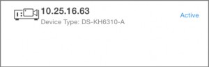
The Mobile Client can detect the online devices in the same local area network with your phone, and you can add the detected online devices to the Mobile Client.
Make sure the devices are connected to the same local area network with the phone.
-
On the device list page, tap
→ Online Device to enter the Online Device page. All detected online devices will be in the list. -
Select a device for adding.

Note
-
For network cameras, make sure the device Multicast Discovery function is enabled so that the online network camera can be automatically detected via private multicast protocol in the LAN. For details, see User Manual of the network camera.
-
For the inactive device (excluding the access control device), tap Active to create a password for it before you can add the device properly. For more information about the device activation, see Set a Password to Activate a Device .
-
-
Optional: Edit the network information.
-
Tap
 .
. -
Change the device IP address to the same LAN as your phone’s by either editing the IP address manually or enabling the device DHCP function.
-
Tap
and input the admin password of the device to save the settings.
-
-
Tap Add.
-
Enter the required information, including device alias, user name and the password.
-
Tap
.
-
Optional: Tap the device name or tap , and then tap Delete Device.
-
-
Add Device(s) by Scanning Device QR Code
You can add the device by scanning the device’s QR code. You can also add device(s) by scanning the QR code obtained via the web page of the device.
-
On the device list page, tap
→ Scan QR Code to enter the Scan QR Code page. -
Scan the QR code.

Note
-
Scan the QR code by aligning the QR Code with the scanning frame.
-
Usually, the device QR code is printed on the label, which is on the back cover of the device.
-
Tap
 to enable the flashlight if the scanning environment is too dark.
-
-
If there are QR codes in photo album of the phone, tap to extract QR code from local album.
-
-
Optional: Perform the following operations if the following situations occur.
-
If the system fails to recognize the QR code, tap
to add the device manually. See Add a Device by Hik-Connect Domain or Add a Device by IP/Domain for details. -
If the device has been added to another account, you should unbind the device from the account first. See Unbind Device from Its Original Account for details.
-
If the device is offline, you should connect a network for the device. For details, see Connect Offline Device to Network for details.
-
If the device is not activated, the Activate Device page will pop up (excluding the access control device). You should activate the device. For details, see Set a Password to Activate a Device for details.
-
If the Hik-Connect service is disabled for the device, you should enable the function (excluding the access control device). For details, see Enable Hik-Connect Service When Adding Device on Mobile Client for details.
-
-
Tap Add on the Result page.
Note
-
Enter the device verification code. The device will be added successfully.
-
The default device verification code is usually on the device label. If no verification code found, enter the device verification code you created when enabling Hik-Connect service.
-
For details about enabling Hik-Connect service, see Enable Hik-Connect Service for Device .

Note
-
-
Optional: Tap Configure DDNS to configure DDNS.
-
After DDNS being enabled, the device will be accessed via IP address in priority, so that remote configuration of the device will be supported and the streaming speed will be faster than streaming via Hik-Connect service.
-
If you skip this step, the device will be accessed via Hik-Connect service.
-
Tap Finish.
-
Optional: Tap the device name or tap
 , and then tap Delete Device.
-
-
You can add the device by fixed IP address or domain name. The streaming speed of devices added by IP/domain is faster than those added by Hik-Connect domain.
If you want to add the access control device, activate it before adding. See the user manual of the access control device for details.
Note
The Mobile Client doesn’t support receiving alarm event information from devices added by IP/ domain. For details about managing event information on the Mobile Client, see Notification
-
Tap
and select Manual Adding. -
Select IP/Domain as the adding type.
-
Enter the required information, such as alias, address, user name, camera No. and device password.
Device IP address or domain name.
The number of the camera(s) under the device can be obtained after the device is successfully added.
Note
-
Tap
to add the device.-
If the device is offline, you should connect the device to a network. For details, see Connect Offline Device to Network .
-
If the device is not activated, the Activate Device page will be popped up (exclude the access control device). You should activate the device. For details, see Set a Password to Activate a Device .
-
-
Optional: Perform the following operations after adding the device.
On the Device Information page, tap
to edit the basic information of the device.Star Live View Tap Start Live View to view the live view of the device.
Delete a Device Tap
and then tap Delete to delete the device.Tap
and then tap Remote Configuration to remotely configure device parameters such as basic information, time settings, recording schedule, etc. See Remote Configuration for details.Remote Controller Tap
and then tap Remote Controller to remotely control the device.See Use Mobile Client as Device’s Remote Controller for details.
-
-
Add a Device by Hik-Connect Domain
For devices which support Hik-Connect service (a cloud service provided by Hikvision), you can add them manually by Hik-Connect domain.
Make sure the device is powered on.
-
On the device list page, tap
→ Manual Adding to enter the Add Device page. -
Select Hik-Connect Domain as the adding type.
-
Enter the device serial No. manually.
Note
-
By default, the device serial No. is on the device label.
-
For the video intercom devices, when entering the serial No. of the indoor station, the corresponding door station will also be added to the Mobile Client automatically.
-
An indoor station can be linked to multiple door stations.

Tap to search the device.
Note
-
If the device has been added to another account, you should unbind the device from the account first. See Unbind Device from Its Original Account for details.
-
If the device is offline, you should connect a network for the device. For details, see Connect Offline Device to Network for details.
-
If the device is not activated, the Activate Device page will pop up (excluding the access control device). You should activate the device. For details, see Set a Password to Activate a Device for details.
-
If Hik-Connect service is disabled for the device, you should enable the function (excluding the access control device). For details, see Enable Hik-Connect Service When Adding Device on Mobile Client for details.
-
-
Tap Add on the Result page.
Note
-
Enter the device verification code. The device will be added successfully.
-
The default device verification code is usually on the device label. If no verification code found, enter the device verification code you created when enabling Hik-Connect service.
-
For details about enabling Hik-Connect service, see Enable Hik-Connect Service for Device .
Note
-
-
Optional: Tap Configure DDNS to configure DDNS.
-
After DDNS being enabled, the device will be accessed via IP address in priority, so that remote configuration of the device will be supported, and the streaming speed will be faster than streaming via Hik-Connect service.
-
If you skip this step, the device will be accessed via Hik-Connect service.
-
Tap Finish.
-
Optional: Tap the device name or tap , and then tap Delete Device.
-
-
-
-
Set a Password to Activate a Device
When adding a device, if the device is not activated, a window will pop up to ask you to activate the device.
The device to be activated and the phone running the Mobile Client should be on the same LAN.
Note
-
Add a device.
See Add Device for Management for details.
-
On the Activate Device page, tap Set Device Password.
Note
-
Create a password.
If you forget the password in the future, you might need to reset the device.
-
Tap Activate to activate the device.
-
Enable DHCP or manually configure network if you enter the Network Configuration page.
-
-
Connect Offline Device to Network
When adding a device to the Mobile Client, if the device is offline, you should connect the device to a network first. The Mobile Client provides the following four methods for connecting offline devices to networks.
Note
Use this method if a router is available for the device to connect to.
Make sure the device is powered on.
Note
Use this method if a wireless network is available for the device to connect to. “Device” here excludes wireless doorbell, wireless security control panel, and Mini Trooper (a kind of battery camera).
-
Make sure your phone has connected to a Wi-Fi network before using the method.
-
The device should support connecting to wireless network.
Connect to Network by Wi-Fi Configuration
You can use this method to connect wireless doorbell to the network by using the doorbell to scan the QR code generated by the Mobile Client.
Tap Connect to a Network on the Result page and then follow the instructions on the subsequent pages to connect the device to the network.
Connect to Network by Access Point
Note
In the Mobile Client, Access Point (AP) refers to a networking hardware device (e.g., wireless doorbell or wireless security control panel), which can provide a Wi-Fi network for the phone to connect to.
Make sure you have turned on WLAN in the phone’s operation system.
Tap Connect to a Network on the Result page, select Wireless Connection as the connection type, and then follow the instructions on the subsequent pages to complete the connection process.
-
-
Enable Hik-Connect Service for Device
Hik-Connect service is a cloud service provided by Hikvision. When adding a device via Hik-Connect Domain or scanning QR code, the service should be enabled. You can enable the service via the Mobile Client, the device web page, or Hik-ProConnect client software. This section introduces how to enable the service via the former two methods.
-
Enable Hik-Connect Service When Adding Device on Mobile Client
When adding a device via Hik-Connect domain or scanning QR code, if the Hik-Connect service is not enabled for the device, the Enable Hik-Connect Service window will pop up to remind you to enable the service first.
Perform the following task to enable the Hik-Connect service in this case.
Note
-
Add a device via Hik-Connect domain or scanning QR code.
See Add a Device by Hik-Connect Domain or Add Device(s) by Scanning Device QR Code for details.
If the device’s Hik-Connect service is not enabled, the following window pops up.
-
On the Enable Hik-Connect Service window, tap Hik-Connect Terms of Service to read the terms of service.
-
Check Read and Agree Hik-Connect Terms of Service.
-
Tap Next.
Note
-
Create a device verification code.
You can change the device verification code. See Change Device’s Verification Code for details.
What to do next
Continue the process for adding the device. See Add a Device by Hik-Connect Domain or Add Device(s) by Scanning Device QR Code for details.
-
-
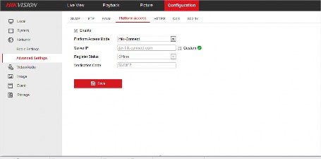
Enable Hik-Connect Service on Device Web Page
You can enable Hik-Connect service for a device on the device web page.
-
Visit the device IP address on the web browser.
-
Enter the device user name and device password to log in to the device web page.
-
Tap Configuration → Network → Advanced Settings → Platform Access to enter the Platform Access page.

-
Check Enable.
The system will set Hik-Connect as the platform access mode by default.
-
Optional: If it is the first time to enable the Hik-Connect service, create a device verification code.
-
Tap Save.
-
-
-
Enable DHCP Function on Device Web Page
You can enable DHCP by following the steps below to allow allocating DNS address automatically.
-
Visit the IP address of the device.
-
Enter the device user name and device password and log in to the device’s web page.
-
Click Configuration → Network → Basic Settings to enter the Basic Settings page.
-
Enable DHCP.
DNS address will be allocated automatically.
-
Click Save.
-
-
Unbind Device from Its Original Account
When adding a device by scanning QR code or Hik-Connect domain, if the result shows that the device has been added to another account, you should unbind it from the account before you can add it to your account.
Make sure the device and the phone running the Mobile Client are in the same local area network.
-
Add the device by scanning QR code or Hik-Connect domain.
See Add Device(s) by Scanning Device QR Code or Add a Device by Hik-Connect Domain for details.
-
On the Result page, tap Unbind Device to start unbind the device from its account.
-
Optional: If the network exception occurs, perform the following operations.
-
Tap Connect to Wi-Fi to connect the phone to the Wi-Fi network and make sure the device is in the same local area network with the phone.
Note
-
Tap Or you can unbind the device from its account in local GUI to unbind the device via local GUI.
Unbinding the device via local GUI should be supported by the device.

-
-
On the Unbind Device page, enter the device password and the verification code displayed on the image.
-
Tap Finish.
-
-
Device Sharing
You can share devices to other users. The recipient can access the devices according to the permissions you grant them. You can also receive and use the devices shared by other users.
-
Share a Device via Its QR Code
You can share a specific device to another Hik-Connect user via the device’s QR code. You can also select the device permissions granted to the recipient to determine which operations the recipient can perform on the device.
-
In the device list, tap
 of the device you want to share.
Note
-
Tap Share with User.
You can share the device with an installer (service provider) to let the installer set up and manage your device. See details in Invite an Installer to Manage Devices .
-
Tap Share via QR Code.
-
Select the device permissions to be shared with the recipient.
-
Check All Permissions to grant all available permissions to the recipient.

-
Tap , and then select permissions to grant the selected ones to the recipient, and finally tap
 .
.For example, if you select Live View and Remote Playback, the recipient will have the permissions to view live video and play back the video footage of the device.
-
-
Let the recipient use the Hik-Connect Mobile Client to scan the QR code.
The recipient needs to send a device sharing application to you. You will receive a notification about the application on your Mobile Client.
-
Agree the device sharing application from the recipient.
-
The device will be shared to the recipient. The recipient will be able to view the device on the device list.
-
The next time you want to share devices to this recipient, you can select the recipient in the History Recipient list.
-
-
Optional: Perform further operations.
-
Go to More → Manage Sharing Settings .
-
Tap the device and then edit the device permissions granted to the recipient.
Stop Sharing a. Go to More → Manage Sharing Settings .
b. Tap the device to enter the Sharing Details page and then tap Delete.
-
-
Share Multiple Devices by Scanning Recipient’s Account QR Code
You can share multiple devices to another Hik-Connect user. You can also set the device permissions granted to the recipient to determine which operations the recipient can perform on the device.
-
Tap
→ Share Device .Note
-
Tap Share with User.
You can share the device with an installer (service provider) to let the installer set up and manage your device. See details in Invite an Installer to Manage Devices .
-
Tap Scan QR Code.
Note
-
Scan the QR code of the recipient’s account.
The recipient needs to go to More → Account Management → My QR Code on the Mobile Client to get the QR code of his/her account.
Note
-
Select the devices you want to share, and then tap Next.
For devices linked with multiple cameras, you can select the cameras for sharing.
-
Select the device permissions to be shared with the recipient.
-
Check All Permissions on the Sharing Details page to select all the permissions.
-
Tap the device displayed on the Sharing Details page, and then select permission(s) and tap
.For example, if you select Live View and Remote Playback, the recipient will have the permissions to view live video and play back the video footage of the device.
-
-
Tap Finish to finish sharing.
A notification about the sharing will appear on the recipient’s Mobile Client. The recipient needs to accept the shared devices.
-
Optional: Perform further operations.
-
Go to More → Manage Sharing Settings .
-
Tap a device and then edit the device permissions granted to the recipient.
Stop Sharing a. Go to More → Manage Sharing Settings .
b. Tap a device to enter the Sharing Details page and then tap Delete.
-
-
Silenced Mode for Devices Shared by Others
You can enable Silenced mode for the devices shared by others if you don’t want to be disturbed by the devices’ alarm notifications. When enabled, all the alarm notifications triggered by the device(s) will be silenced. And you can still check the information of all the silenced alarm notifications from the devices on the notification list.

Tap to enter the Settings page of the device and then enable the Silenced mode.
-
-
Favorites Management
You can add the frequently-used camera(s) to the favorites so that you can access them conveniently.
-
Add Cameras to Favorites on Home Page
On the device list page, you can add the frequently-used camera(s) to the favorites so that you can access them conveniently.
-
On the home page (Hik-Connect page), tap
. -
Tap Add to Favorites.
-
Select devices and cameras on the Select Camera page.
-
Tap OK.
Note
-
Create a name for the Favorites and then tap OK.
-
Up to 32 favorites can be added.
-
The favorites name should be no more than 32 characters.
The added Favorites will be displayed on the device list page.
-
-
Optional: Tap the Favorites name on the home page to view the cameras’ live videos.
-
-
Add Cameras to Favorites During Live View
On the live view page, you can add frequently-used cameras to Favorites so that you can access them conveniently
Note
-
Enter the Live View page.
For details about how to enter the Live View page, see Start and Stop Live View
-
Tap
 and tap Add to Favorites.
 -
Add cameras to favorites.
-
Create a new favorites in the pop-up window and tap OK.
-
Add to existing favorites.
-
Tap Add to Existing Favorites in the pop-up window.
Note
-
Select a Favorites folder in the list.
-
Up to 32 Favorites can be added.
-
The favorites name should be no more than 32 characters.
-
-
-
Optional: Tap the Favorites on the device list page to view the cameras’ live videos.
-
-
Remove Cameras from Favorites
You can delete cameras in the favorites.
-
Tap of the Favorites.
-
Tap a camera that need to be deleted.
-
Tap Confirm in the pop-up window to delete the camera.
-
-
-
Device Settings
Note
On the Settings page of a device, you can view and edit the device’s basic information, delete the device, upgrade device firmware, and configure other functions such as video and image encryption and changing device verification code.
The available functions on the Settings page vary with different device types and device models.
-
Change Device’s Verification Code
The device verification code is used for verifying user identity, as well as encrypting a device’s videos (including live videos and recorded video files) and captured pictures. You can change the device verification code for the network camera and Mini Trooper (a kind of camera powered by battery).
Note
For details about how to encrypt a device’s videos and captured pictures, see Set Video and Image Encryption .
-
On the device list page, tap to enter the Settings page of the device.
-
Tap Change Verification Code, and then tap Edit on the pop-up Window to enter the Change Verification Code page.
-
Enter the old verification code, and then tap Next.
Note
-
Create a new verification code, and then confirm it.
If you have enabled the Video and Image Encryption function, new pictures and videos will be encrypted by the new verification code. However, the earlier encrypted pictures and videos still use the old verification code.
-
-
Set Video and Image Encryption
For security reasons, you can set the video and image encryption function to encrypt the videos or the pictures.
Note
-
If you set the video and image encryption function, the device’s live video, recorded video, and pictures in event information will be encrypted. You should enter the device verification code the first time you entering these pages.
-
If you log in to the Mobile Client with the same account on another phone, you should enter the device verification code again to view the live video, the recorded video, and pictures in event information.
-
On the device list page, tap to enter the Settings page of the device.
-
Set the Video and Image Encryption switch to ON to enable the function.
-
Optional: Change the encryption password (device verification code).
-
Tap Change Password.
-
Tap Edit in the pop-up window to enter the Change Password page.
Note
-
Follow the instructions on the page to change the device verification code.
-
The default device verification code is usually on the device label. If no verification code found, enter the device verification code you created when enabling Hik-Connect service. For details about enabling Hik-Connect service, see Enable Hik-Connect Service for Device .
-
-
-
For a device added via Hik-Connect Domain or Scaning QR code, if DDNS is enabled, the device’s streams will be accessed via IP address in priority. In this case, you can remotely configure device and the speed of streaming will be faster than that of streaming via Hik-Connect service.
-
On the device list page, tap to enter the Settings page of the device.
-
On the Settings page, tap Configure DDNS to enter the Configure DDNS page.
-
Set the required information.
The default device domain name is the serial number of the device. If you want to edit it, the edited domain name should contain 1 to 64 characters, including numbers, lowercase letters, and dashes. And it should start with a lowercase letter and cannot end with a dash.

Note
For details about setting port mapping, tap How to Set Port Mapping.
The entered port number should be from 1 to 65535.

Enter the device user name.
Enter the device password.
-
Tap
.
-
-
You can upgrade the firmware of a device to its latest version. If the latest version is detected, a red dot will appear on the Device Version field of the Settings page of the device.
-
On the device list page, tap to enter the Settings page of the device.
-
Tap Device Version to enter the Device Version page.
-
Tap Upgrade.
Note
The Mobile Client will download the upgrade file first and then start upgrading the device.
You can also enable the Mobile Client to automatically download the upgrade file in Wi-Fi networks once a new device version is detected. For details, see Auto-Download Upgrade File .
-
-
You can select a recorded audio file and set it as the custom audio prompt for the alarms sent from the channels linked to specific models of DVR.
Make sure you have recorded audio files on the Mobile Client. For details, see Manage Custom Audio .
Note
The device should support this function.
-
On the device list, tap
to enter the Settings page of the device. -
Tap Custom Audio to enter the Select Channel page.
-
Select channel(s), and then tap Next Step. The available audio file(s) will appear.
-
Optional: Tap the Play icon to play the audio file.
-
Select an audio file, and then tap OK.
-
-
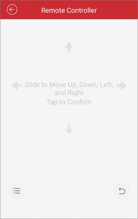
Use Mobile Client as Device’s Remote Controller
For a device added via IP/Domain, you can use the Mobile Client as the device’s remote controller.
Note
-
The function should be supported by the device.
-
The remote controller function is supported when your phone is connected to a Wi-Fi network, and the network latency should be less than 200ms.
-
On the device list page, tap to enter the Settings page of the device.
-
Tap
and tap Remote Controller to enter the following page.
-
Swipe the screen to perform remote-control operations such as moving up, down, left, and right.
-
Tap the screen to confirm.

-
Optional: Tap to cancel and return to the previous menu of the device.
-
Optional: Tap to open the main menu of the device.
-
-
-
-


After adding a device, you can set the parameters of the device, including basic information, time settings, recording schedule, etc.
View and Edit Basic Information
You can view and edit the basic information of a device.
Add a device to the Mobile Client. See Add Device for Management for details.
![]()
-
On the device list page, tap to enter the Settings page of the device.
-
Enter the Remote Configuration page.
Note
-
For a device added via IP/Domain, tap
→ Remote Configuration .For details about adding device via IP/Domain, see Add a Device by IP/Domain .
Note
-
For a device added via other methods, tap Remote Configuration on the Settings page.
You should have configured DDNS for the device first. See Set DDNS .

-
-
Tap Basic Information to enter the Basic Information page.
-
Tap
to enter the Edit Device page. -
Edit the basic information of the device.
-
Tap
to save the settings.

You can set a recording schedule for a channel of a specific device.
![]()
-
On the device list page, tap to enter the Settings page of the device.
-
Enter the Remote Configuration page.
Note
-
For a device added via IP/Domain, tap
→ Remote Configuration .For details about adding device via IP/Domain, see Add a Device by IP/Domain .
Note
-
For a device added via other methods, tap Remote Configuration on the Settings page.
Make sure you have configured DDNS for the device first. See Set DDNS .
-
-
Tap Recording Schedule to enter the Recording Schedule page.
-
Select a channel if the device has multiple channels.
-
Set the switch to ON to enable recording schedule.
-
Set a recording schedule for a day in the week.
-
Tap a day in the week to enter the schedule settings page.
-
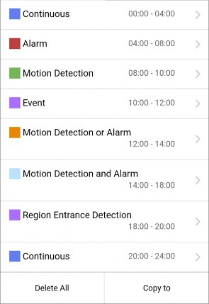
Tap a time period to set the recording type, start time, and end time.
The video will be recorded automatically according to the time of the schedule.
The video will be recorded when the motion is detected.
The video will be recorded when the alarm is triggered via the external alarm input channels.
The video will be recorded when the external alarm is triggered or the motion is detected.
The video will be recorded when the motion and alarm are triggered at the same time.

Note
The video will be recorded when any event is detected.
You can also set the recording type to detailed event type, which should be supported by the device. For details, refer to the user manual of the device.

-
Tap OK to save the settings of the time period.
Note
-
Set other time periods in the day.
Up to 8 time periods can be configured for each day. And the time periods cannot be overlapped with each other.

-
-
Optional: Perform the following operations after saving the time periods in one day.
Tap Copy to to copy all the time periods settings to the other days in the week.
Delete All Tap Delete All to clear all the configured time periods.
-
Tap
to save the settings.

You can select the time zone and set the time synchronization mode to Manual or NTP mode for the added device.
![]()
-
On the device list page, tap to enter the Settings page of the device.
-
Enter the Remote Configuration page.
-
For a device added via IP/Domain, tap → Remote Configuration .
Note
For details about adding devices via IP/Domain, see Add a Device by IP/Domain .
Note
-
For a device added via other methods, tap Remote Configuration on the Settings page.
You should have configured DDNS for the device first. See Set DDNS .
-
-
Tap Time Configuration to enter the Time Configuration page.
-
Select the time zone in which the device locates. The device time will be adjusted automatically.
-
Select the time synchronization mode.
-
Select NTP Synchronization. And then set the interval for synchronizing the device time with the NTP server.
Note
Synchronize time at a specific interval with the NTP server.
For details about setting the NTP server details, refer to the user manual of the device.

-
Select Manual Synchronization. And then tap Synchronize with Phone to synchronize the device time with the OS (Operation System) time of your phone.
-
-
Tap
to save the settings.

You can change the password of a device via the Mobile Client.
![]()
-
On the device list page, tap to enter the Settings page of the device.
-
Enter the Remote Configuration page.
Note
-
For a device added via IP/Domain, tap
→ Remote Configuration .For details about adding device via IP/Domain, see Add a Device by IP/Domain .
Note
-
For a device added via other methods, tap Remote Configuration on the Settings page.
You should have configured DDNS for the device first. See Set DDNS .
-
-
Tap Change Password to enter the Change Password page.
-
Enter the old password of the device
-
Create a new password.

Caution
The password strength of the device can be automatically checked. We highly recommend you change the password of your own choosing (using a minimum of 8 characters, including at least three kinds of following categories: upper case letters, lower case letters, numbers, and special characters) in order to increase the security of your product. And we recommend you change your password regularly, especially in the high security system, changing the password monthly or weekly can better protect your product.
Proper configuration of all passwords and other security settings is the responsibility of the installer and/or end-user.
-
Confirm the password.
-
Tap
to save the changes.

You can enable a device’s normal event such as motion detection, video tampering alarm, video loss alarm, for the channels of the device.
![]()
-
On the device list page, tap to enter the Settings page of the device.
-
Enter the Remote Configuration page.
Note
-
For a device added via IP/Domain, tap
→ Remote Configuration .For details about adding device via IP/Domain, see Add a Device by IP/Domain
Note
-
For a device added via other methods, tap Remote Configuration on the Settings page.
You should have configured DDNS for the device first. See Set DDNS .

-
-
Tap Normal Event to enter the Normal Event page.
-
Optional: Select a channel if the device has multiple channels.
-
Set the switch(es) to ON to enable the event(s).

You can enable the smart event for the channels of a device, including audio exception detection, face detection, and intrusion detection, etc.
![]()
Note
The supported event types of smart event vary according to different devices.
![]()
![]()
-
On the device list page, tap to enter the Settings page of the device.
-
Enter the Remote Configuration page.
Note
-
For a device added via IP/Domain, tap
→ Remote Configuration .For details about adding device via IP/Domain, see Add a Device by IP/Domain .
Note
-
For a device added via other methods, tap Remote Configuration on the Settings page.
You should have configured DDNS for the device first. See Set DDNS for details.
-
-
Tap Smart Event to enter the Smart Event page.
-
Optional: Select a channel if the device has multiple channels.
-
Set the switch(es) to ON to enable event(s).

Enable Temperature Measurement
You can enable the temperature measurement function for the thermal camera on the Mobile Client.
![]()
Note
This function is only available to the thermal camera.
![]()
![]()
-
On the device list page, tap to enter the Settings page of the device.
-
Enter the Remote Configuration page.
Note
-
For a device added via IP/Domain, tap
→ Remote Configuration .For details about adding device via IP/Domain, see Add a Device by IP/Domain .
Note
-
For a device added via other methods, tap Remote Configuration on the Settings page.
You should have configured DDNS for the device first. See Set DDNS .
-
-
Tap Temperature Measurement to enter the Temperature Measurement page.
-
Optional: Select a camera if camera(s) are linked to the device.
-
Set the switch to ON to enable temperature measurement.

Chapter 4 Cloud Service
In Cloud Service, you can manage or access services related to Hik-ProConnect, which is a cloud service platform for Installers (installation companies). Installer can provide services such as device configuration and device maintenance for you if granted with device authorization and permissions. You can manage device authorization and permissions in Cloud Service.
Cloud Service page includes the following modules.
Check cloud-related notifications and respond requests from Hik-ProConnect, such as applications from the Installer, including applications for device handover, device authorization and permissions, and device password reset.
Manage device authorization, device permissions, and ARC authorization, check Installer information, and transfer devices to another user.
Check the devices that are deauthorized from the Installer and re-authorize to a new or existing Installer.
![]()
Note
Access the features activated by your Installer via Hik-ProConnect, including Access & Attendance, People Counting, and Temperature Screening.
-
Cloud features are not available in all countries or regions.
-
Installer can also activate cloud storage for your devices. With cloud storage, you can easily access the video footage of your video devices stored on cloud. See details in Cloud Storage .
![]()
-
-
Invite an Installer to Manage Devices
You can invite and authorize an installer to help you set up and manage the devices in your account.
-
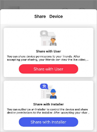
In the device list, tap
of the device and the Share Device page will pop up.
Note
If you cannot see this page, it means the device cannot be managed by an Installer and can only be shared with another Hik-Connect user.
Possible reasons: the device is shared from others; the device is already managed by an Installer; the Hik-Connect service is not enabled for the device; the Hik-ProConnect service (Installer service) is not available in your country or region.
-
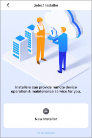
Tap New Installer and enter the installer’s account if you want to share device permissions with a new installer or you do not have an installer before. You can also select an existing installer if you have authorized one or more installer to manage your other devices before.

-
Select the site which the device will be added to and the device permissions you want to grant to the installer.

Note
-
If the installer has not created any site for your devices, a new site will be created.
-
What’s a Site? A site is like an area where your devices are located, such as your home, office, etc. Your installer uses sites to group, batch configure, and provide cloud features for your devices.
-
-
Tap OK to invite the installer.
Your installer will receive an email about the authorization and need to accept it before managing your device on Hik-ProConnect.
-
-
Device Authorization Management
You can grant authorization and permissions of the devices in your Hik-Connect account to an Installer. With device authorization and permissions, the Installer is able to control and configure the devices, thereby managing and maintaining the devices for you.
You can manage device authorization in Cloud Service → Device Authorization .
Note
-
If you have multiple Installers, you can tap on Installer’s name at the top to switch between Installers.
-
Authorized devices are grouped in “Sites” which are created by your Installer.
-
If your Installer has sent device authorization application to you, you can grant authorization by approving the application. See Approve Device Handover and Authorization Application for details.
-
To authorize an Installer with more devices, follow the steps below.

-
Bulk Edit the Permissions of Devices in a Site:
Tap → Edit Device Permissions . Select devices and edit the permissions.
-
Edit the Permissions of a Single Device:
Go to the Home page, in the device list, tap
of a device to enter the device settings page. TapAuthorization Service → Edit Permission to edit device permissions.
Tap → Cancel Authorization to cancel the authorization of all devices in the Site. You can keep the Site if there are value-added services activated.
Deauthorized Sites and devices are in the Deauthorized Devices page. You can share Site ID or QR code to another Installer to resume the services.
-
-
Reset Password of Device in Authorization
Note
You can reset the password of a device with the assistance of Installer.
This feature requires device support.
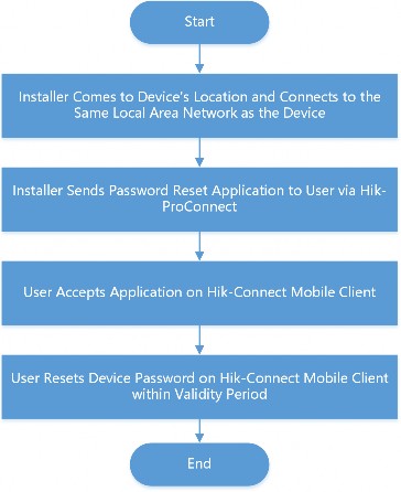
Refer to the flow chart below for the whole process of resetting the password of a device that you authorized Installer with.

Note
Figure 4-4 Flow Chart of Resetting Device Password
-
The validity period of password reset application is 5 minutes.
-
You will be notified whether password reset is completed or failed.
User can ask the Installer for a password reset if the password of an authorized device is lost. The Installer has to go to the device’s location and connect to the same local area network before sending a password reset application to the user. After the Installer sends the password reset application, user can set a new password for the device.
-
-
Transfer Device to Others
You can transfer the devices in your account to another account. Once transferred, the devices will be unavailable to you, and the target account will have all configuration and operation permissions of the devices.
-
Go to Cloud Service → Device Authorization .
Note
-
Tap → Transfer Device .
Only supports transferring devices in a Site altogether. Site is created by your Installer to group your devices.
-
Enter the mobile phone number or e-mail address of the target account.
Note
-
Tap OK to start transferring.
-
The Site becomes unavailable during transfer process.
-
The recipient will receive a device transfer application. You can cancel device transfer before the target user accept the application. Once the recipient accepts it, you will no longer have any access or permission towards the devices.
-
If the devices are managed by an Installer, the recipient can choose to keep the authorization service or cancel it.
-
If the recipient choose to keep the current authorization, the Installer managing the device will still have the device permissions after the transfer.
If the recipient choose to cancel the authorization, the Installer will not have any permission of the device after the transfer.
-
-
ARC Service
ARC stands for Alarm Receiving Center. ARC provides round-the-clock alarm monitoring and responding service for you. ARC can receive event notifications sent from your devices and respond to these events. In case of emergency, such as intrusions or fires, ARC sends out dispatches or contact the police on your behalf to address security issues to protect people and property.
Note
ARC service is not available in all countries or regions.
Your Installer can enable ARC service for you with your approval.
To enable ARC service, the Installer needs to applies for ARC authorization and permissions. After the Installer sends an application, you need to accept it to activate the ARC service. See Approve Device Handover and Authorization Application for instructions.
To check the currently active ARC service, go to Cloud Service → Device Authorization .
You can deactivate ARC service by deauthorizing ARC.
To deauthorize ARC, go to Cloud Service → Device Authorization → Alarm Receiving Center (ARC)
and click Deauthorize.
After deauthorization, the ARC will lose all device permissions you granted previously and cease to provide ARC service for you.
-
Cloud Attendance
Note
Cloud Attendance works with MinMoe access control devices. It is designed for bringing higher security and improved efficiency to access control and attendance tracking. Persons in a cloud attendance system (usually employees in an organization) can use Cloud Attendance on the Mobile Client to check attendance records, control doors and turnstiles, and check in/out.
-
Cloud Attendance is not available in all countries or regions.
-
If applicable, make sure you have evaluated the impact on data protection before using Cloud Attendance.
-
Select your role and read the part you need.
-
If you are the employee who needs to check attendance records and control doors, read the
For Employee section.
-
If you are the administrator who needs to set up the Cloud Attendance system, read the For Administrator section.
Note
Go to Cloud Service → Cloud Attendance .
If you cannot see Cloud Attendance in the Cloud Service tab, you are not in a Cloud Attendance system. Ask the administrator of the Cloud Attendance system for help.
Cloud Attendance has three tabs:
Check your attendance status and records.
Check in or check out directly on the Mobile Client without actually presenting and authenticating at the attendance check devices. See details in Check In/Out Remotely .
See the live view of an access control device and open door remotely. See details in Open Door Remotely .
Note
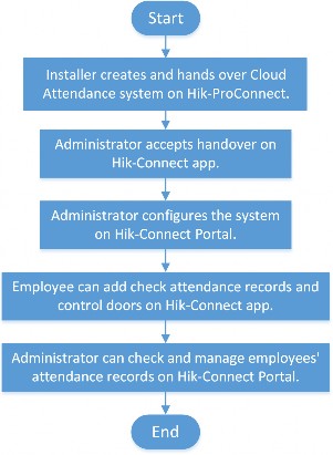
If you are the administrator who manages employees’ attendance, you need to set up the Cloud Attendance system before the employees can use Cloud Attendance via the Hik-Connect Mobile Client. The system contains the access control devices, person information, shift settings, and access permission settings.
An Installer can create such a system, add access control devices into the system, and hand it over to you. Contact your Installer if you want to deploy Cloud Attendance in your organization.
The following is the flow chart for deploying Cloud Attendance:

Figure 4-5 Flow Chart for Deploying Cloud Attendance
-
-
-
You can check in or check out directly on the Mobile Client without actually presenting or authenticating at an attendance check device.
Ask Administrator to Enable Check-In/Out on Mobile Client
If you cannot see the Check In tab, it means that you do not have the permission to check in/out on the Mobile Client yet.

Figure 4-6 Check In Tab in Cloud Attendance
You can ask the administrator of the attendance system to enable Check-In/Out by Mobile Client for you on the Hik-Connect Portal. The administrator also needs to set the locations of each attendance site and the valid check-in range.
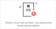
If the attendance system has no attendance check device added, you cannot check in/out on the Mobile Client even if the feature is enabled for you.

Figure 4-7 No Attendance Check Device
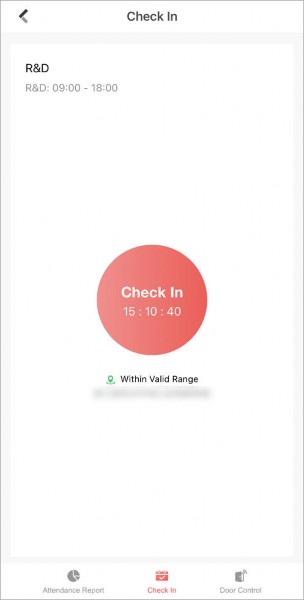
Check In/Out on the Mobile Client
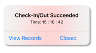
If you have acquired the permission to check in on the Mobile Client, you can tap Check In
whenever you are within the valid check-in range of any attendance site. After checking in/out, you can view the recent attendance records.

Figure 4-8 Pop-Up Notice on Recent Check-In/Out
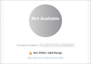
If You are not Within Valid Range…
If you are not within the valid check-in range of any attendance site, check-in/out will be unavailable.

Figure 4-9 Check-In/Out Unavailable
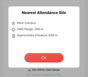
You can tap See Nearest Attendance Site to check the nearest site for checking in/out.

Figure 4-10 See Nearest Attendance Site
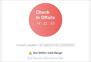
If You are Working from Home or on a Business Trip…
If you are not required to work at a fixed location, the administrator can enable Allow Offsite Check-In for you.
You can tap Check In Offsite to check in outside the valid check-in range of any attendance site.

Figure 4-11 Check In Offsite
-
You can control the status of doors in the Cloud Attendance system. You can also see the live video of a door before you open it.
Make sure the administrator has granted the following permissions to you: Remotely Open Door and Remote Live View.
-
Go to Cloud Service → Cloud Attendance → Door Control . You can see the live view of the access control devices.
-
Control door status.
Keep the door open.
Open the door temporarily.
Keep the door closed.
-
-
-
The administrator of the Cloud Attendance system can add a face picture in your person information, so that you can use face recognition for access control and time attendance. If the administrator did not add a face picture for you, you can add it by yourself.
Note
If you are the administrator of the Cloud Attendance system, use Hik-Connect Portal to add employees’ face pictures. You shall ensure that you have obtained the explicit consent from the data subject before you upload the face image and that you have performed the DPIA (Data Protection Impact Assessment) where applicable beforehand.
-
Tap
 to enter person information page.
 -
Tap Add Face Picture and follow the instructions on screen to finish the process.
-
-
-
-
People Counting
Note
People Counting works with people counting cameras. It is designed for monitoring crowd density in order to achieve “social distancing” in workplaces, businesses, and public spaces. On the Hik- Connect Mobile Client, you can see the real-time number of people staying in an area, set the maximum number of people allowed to stay in the area, and get alerts when more people are present.
Contact your Installer if you want to deploy People Counting in your space.
To check over-limit records, tap Message and Report. You can filter the records by dates and people counting groups.
Note
-
An over-limit record contains information such as the name of people counting group, device name, alarm time, actual number of people, and the alarm threshold you set.
-
Over-limit records can be kept for up to 30 days.
Note
To send a copy of the records, tap
and enter your email address.The records will be saved as an Excel file.
-
-
Temperature Screening
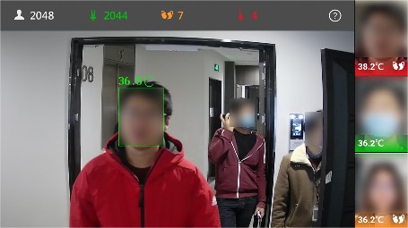
Temperature Screening works with temperature screening devices and thermographic cameras. It is designed for contact-less skin-surface temperature measurement and detection of protective face masks so as to achieve preliminary screening in public areas with high efficiency. On Hik- Connect Mobile Client, you can see the screening results in real-time, set a threshold temperature, and receive abnormal temperature alarms and no-mask alarms.

Note
Figure 4-12 Temperature Screening and Mask Detection
-
Temperature Screening is not available in all countries or regions.
-
Contact your Installer if you want to deploy Temperature Screening in your space.
To check the records of abnormal temperature alarms and no-mask alarms, tap Message and Report. You can filter the records by dates, alarm types, and devices.
Note
An alarm contains information such as device name, alarm time, alarm type, and body temperature.
Note
To send a copy of the records, tap
and enter your email address.The records will be saved into an Excel file.
-
-
Service Notification
-

![]()
Note
In Cloud Service → Service Notifications , you can view the notifications related to services offered by your Installer via the Hik-ProConnect platform, including applications for device handover, device authorization and permissions, and device password reset. You can also view notifications about cross-device linkages, device exceptions and corresponding handling results, and logs about Installer’s operations on your devices.
Hik-ProConnect is a cloud service platform for the Installers (installation companies) that configure and maintain your devices and provide value-added services for you.
![]()
-
-
-
Accept Invitation to Be Site Owner
You can accept the invitation from the Installer to be the owner of a specific site.
You can tap View Details on an invitation to view the details such as the site and the devices authorized to the Installer, and then tap Agree to accept the invitation and therefore become the owner of the site.
-
Approve Device Handover and Authorization Application
If an Installer hands over devices to you or applies for device permissions on the Hik-ProConnect platform, you will receive an application notification. After you approve the application, the Installer will be able to provide device configuration and maintenance services based on the permissions you granted.
-
If the Installer hands over devices to you, you will receive device handover and authorization applications.
-
If the Installer applies for device permissions, you will receive device authorization applications.
-
Go to Cloud Service → Service Notifications .
-
Tap on a Device Handover and Authorization Application notification.
Note
-
Accept device handover.
After handover, your Installer does not have any permissions to operate or configure the devices. Installer usually applies for device permissions so as to configure and maintain the devices for you. If your Installer has applied for the permissions, you need to accept it in device authorization application.
-
Open the Device Authorization Application.
-
If the Installer has applied for device permissions when handing over the devices, the device authorization application will show up right after you accept device handover.
Note
-
If the Installer has not applied for device permissions, open the application after the Installer sends one.
-
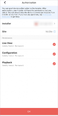
In device authorization application, you can view details such as Installer information, permissions that the Installer applies for, and the Alarm Receiving Center (ARC) information.
-
For more details on Alarm Receiving Center, see ARC Service .
Note
-
-
-
Select the permissions you want to grant to the Installer.
-
If the Installer enabled ARC service for you, you can check ARC Service to activate it.
-
If you activate ARC service, the ARC will provide 24/7 alarm responding service for you, including receiving events from devices, responding to events, and sending out emergency dispatches (if needed).
-
-
Tap Agree to approve the application.
-
-
-
Notification about Availability of a Rent Device
Note
If a device that you rent from the Installer is blocked or unblocked by the Installer, you will receive a notification about that.
If a rent device is blocked by the Installer, you are not allowed to operate the device via the Mobile Client. In this case, you can contact the Installer and ask her/him to unblock the device if required.
For such a notification, you can view the Installer who block/unblock the device and the site where the device is added.
-
Linkage refers to the process in which an event detected by a resource triggers actions in other resources. The linkage can be used for notifying security personnel, upgrading security level, saving
Note
evidence, etc., when specific events happen. You can view notifications about linkages in Service Notifications.
-
This feature is not available in all countries or regions.
-
The linkage can only be set by the Installer via the Hik-ProConnect platform.
Note
Go to Cloud Service → Service Notifications → Linkage to view linkage notifications. You can tap on each notification to view the detected event, event time, devices in the linkage, and triggered actions.
If the Installer has not set linkages for your devices, or the pre-defined linkage actions has not been triggered once, the Linkage tab will not show in Service Notifications.
-
-
-


You can receive and view the exception notifications of your devices that are managed by the installer.
After your installer handles an exception, you will also be notified of the handling result. You can see all exception notifications in Cloud Service → Service Notifications → Linkage .
Chapter 5 Video & Cloud Storage
With the Mobile Client, you can remotely view live videos of the added encoding devices (e.g., cameras, NVRs,and DVRs) and play back their video footage. If cloud storage is activated on the video devices, you can browse, search, play back, and download the video footage on cloud.
-
-
Live View
You can view live video of the devices’ connected cameras. And some basic operations are supported during live view, including picture capturing, manual recording, PTZ control, etc.
-
Live view shows you the live video getting from cameras. Perform the following task to start and stop live view.
-
Tap a camera to enter the Live View page.
-
If the Video and Image Encryption function is disabled, the live video will start playing automatically.

Note
-
If the Video and Image Encryption function is enabled, you should enter the device verification code before the live video starting playing.
-
For details about Video and Image Encryption function, see Set Video and Image Encryption .
-
The default device verification code is usually on the device label. If no verification code found, enter the device verification code you created when enabling Hik-Connect service.
-
The live video from the video intercom device lasts 5 minutes.
-
Up to 6 users can view the live video of a same door station simultaneously. If the upper- limit is reached, other users can only use the audio function of the door station.
-
-
-
Optional: Perform the following operations.
Rotate the phone to view live video in full screen mode.
Switch Camera Swipe the live view page to the left or right to switch camera and view its live video.
-
Tap
to go back to the device list. -
Reselect cameras and then tap OK.

Note
You can select up to 256 cameras.


Note
Switch to Playback Tap
→ Playback to switch to playback.For details about playback, see Playback .

-
-
Stop live view of a camera.
-
Press and hold a window under live view.
-
Drag the window upwards to the appearing
at the top of the page.
-
-
You can adjust window division in different scenarios.
Tap
 ,
,  , , or to set the window division mode to 1-window, 4-window, 9-window, 12-window, or 16-window respectively.
If the added camera number is more than the window division number, you can swipe left or right to see the rest.
-
Digital zoom adopts encoding technology to enlarge the image which will result in image quality damage. You can zoom in or zoom out the live video image as desired.
Tap
to zoom in or zoom out the image.Or spread two fingers apart to zoom in, and pinch them together to zoom out.
-
Note
PTZ is an abbreviation for “Pan, Tilt, and Zoom”. With the PTZ Control functionality provided by the Mobile Client, you can make the cameras pan and tilt to the required positions, and zoom in or out the live video images. For some network cameras, you can also enable auto-tracking to make the camera pan, tilt, and zoom to track the detected moving objects.
PTZ control should be supported by the camera.
The Mobile Client allows you to pan and tilt a camera’s view.
Note
-
Start live view of a camera supports PTZ control.
For details about how to start live view, see Start and Stop Live View .
-
Select a live view window on the Live View page.
-
Tap
to open the PTZ Control panel.
-
Tap Pan and Tilt.
-
Drag the circle button at the center of the PTZ Control panel to pan and tilt the camera.
A preset is a predefined image position which contains configuration parameters for pan, tilt, zoom, focus and other parameters. You can also set a virtual preset after enabling digital zoom. After you set a preset, you can call the preset and then the camera will move to the programmed position.
Note
-
Pan and tilt a camera to move the camera direction to a desired position.
See Pan and Tilt a Camera for details.
-
In the PTZ Control panel, tap Add Preset to open the following window.

Note
-
Swipe the number up or down to set the preset No.
The preset No. should be between 1 and 256.
-
Tap Set to complete setting the preset.
-
Tap Call to call the preset.
-
Optional: Tap Delete to delete the preset.
You can adjust the PTZ speed.
-
Start live view of a camera which supports PTZ control.
-
Tap to open the PTZ control panel.
-
Tap More → to open the PTZ speed panel.
-
Drag the slider to adjust the PTZ speed.
The PTZ Control panels provide other functions such as PTZ speed adjustment, auto-scan, focus control, iris control, and auto-tracking.
Tap More on the PTZ Control panel to view the functions.
Table 5-1 Other Functions
Icon
Description
Start/stop the auto-scan, which means to make the speed dome pan, tilt, and (or) zoom by a predefined route.
 Note
Note
Zoom control:
Zoom+/
Zoom-

Focus control:
Focus +/
Focus –
Iris control:
Iris +/ Iris –-
You can define the route on the device. For details, see the user manual of the device.
-
The function should be supported by the device.
Icon
Description
Adjust PTZ speed.
Enable/Disable auto-tracking. After enabled, when the camera detects a moving object, the camera will pan, tilt, and zoom to track the object until the object moves out of the field of view of the camera.
NoteThe function should be supported by the device.
-
-
Two-way audio function enables the voice talk between the Mobile Client and devices. You can get and play not only the live video but also the real-time audio from the devices, and the devices can also get and play the real-time audio from the Mobile Client.
Note
-
The function should be supported by the device.
-
The devices added by Hik-Connect domain or by scanning QR code do not support this function.
Note
-
Start live view of the device.
See Start and Stop Live View for details.
-
Tap in the toolbar to turn on the two-way audio.
Note
-
If the device is a NVR, select the device or its linked network camera as the two-way audio channel.
If not, skip this step.
-
If the device is full duplex, two-way audio will be started automatically.
-
If the device is half-duplex, you have to tap and hold
 to talk, and release to listen.
-
-
Tap
 to turn off two-way audio.
-
-
-
During live view, you can capture pictures of the live video and record video footage.
Note
-
Start live view of a camera.
See Start and Stop Live View for details.
-
Capture a picture or record video footage.
Capture Picture Tap
to capture a picture.Record Video Footage Tap
 to start recording video footage, tap again to stop.
The captured pictures and recorded videos will be saved in More → Pictures and Videos . For details about managing pictures and videos, see Pictures and Videos .
-
-
Set Image Quality for Device Added by IP/Domain
For devices added via IP/Domain, you can set its image quality to Fluent or Clear. You can also customize image quality for the devices.
Note
-
If you change the image quality, the live view and recording of the device may be affected due to the new settings.
-
In multi-window mode, you can only set the image quality to Fluent, or customize the image quality and the stream type can only be Sub Stream.
Note
1. Start live view of a device added via IP/Domain.
See Start and Stop Live View for details.

Tap
on the live view page to enter the quality switching panel.
Note
The icon vary with the actual video quality.
-
Set the image quality as desired.
-
Tap Clear to set the image quality as Clear.
-
Tap Fluent to set the image quality as Fluent.
-
Tap Custom to open the Custom Settings window, and then configure the parameters and tap
-
Confirm to confirm the custom settings.
Note
-
The live view effect is related to the performance of your network and hardware of your network and phone. If the live view is not fluent or the image appears blurred, reduce the resolution, frame rate and bitrate of the camera in custom mode, or set the image quality as fluent mode.
-
The following table shows the recommended frame rate and bitrate configuration for different resolution at H.264, H.264+ and H.265 video compression by using iPhone 5S.
Table 5-2 Recommended Configuration
Resolution
1-ch
2-ch
4-ch
Recommended Configuration
H.264 (Hardware Decoding)
1080P
√
√
√
Frame rate: 25fps; Bit rate: 4Mbps
720P
√
√
√
Frame rate: 25fps; Bit rate: 2Mbps
4CIF
√
√
√
Frame rate: 25fps; Bit rate: 512Kbps
H.264 (Software Decoding)
720P
√
√
Frame rate: 25fps; Bit rate: 2Mbps
4CIF
√
√
√
Frame rate: 25fps; Bit rate: 512Kbps
H.264+ (Hardware Decoding)
1080P
√
√
√
Frame rate: 25fps; Bit rate: 4Mbps
720P
√
√
√
Frame rate: 25fps; Bit rate: 2Mbps
H.264+ (Software Decoding)
720P
√
√
Frame rate: 25fps; Bit rate: 2Mbps
H.265 (Software Decoding. Hardware decoding is not supported.)
1080P
√
Frame rate: 25fps; Bit rate: 2Mbps
720P
√
√
Frame rate: 25fps; Bit rate: 1Mbps
4CIF
√
√
√
Frame rate: 25fps; Bit rate: 256Kbps
-
-
-
Set Image Quality for Hik-Connect Device
Usually three pre-defined image qualities are provided in the Mobile Client for Hik-Connect device: Basic, Standard, and High Definition.
Note
The provided image quality types may vary with different devices.
Note
1. Start live view of a Hik-Connect device.
See Start and Stop Live View for details.
Tap
to enter the quality switching panel.
Note
The icon may vary with the actual image quality.
3. Set image quality.
Note
Basic image quality.
Basic is the default image quality.
Standard image quality (the image quality is higher than that of Basic and lower than that of HD).
High definition image quality (the image quality is the highest of the three).
-
In the fisheye view mode, the whole wide-angle view of the fisheye camera is displayed. Fisheye expansion can expand images in five modes: 180° panorama, 360° panorama, 4-PTZ, semisphere, and cylindrical-surface.
Note
The function is only supported by fisheye camera.
Note
1. Start live view of a fisheye camera.
See Start and Stop Live View for details.
Tap to show the fisheye expansion panel.
-
Select mounting type.
Icon
Description

Wall Mounting
Ceiling Mounting
-
Select fisheye expansion mode.
Table 5-4 Fisheye Expansion Mode
Icon
Description

Fisheye view for ceiling mounting and wall mounting. In the Fisheye view mode, the whole wide-angle view of the camera is displayed. The mode is the vision of a fish’s convex eye. The lens produces curvilinear images of a large area, while distorting the perspective and angles of objects in the image.
In this mode, you can pinch the fingers together to zoom out the image, and spread them apart to zoom in.

Dual-180° panorama view for ceiling mounting. The distorted fisheye image is transformed to normal perspective image.
In this mode, you can swipe to the left or to the right to adjust the field of view.
360° panorama view for ceiling mounting and wall mounting. The distorted fisheye image is transformed to normal perspective image.
In this mode, you can swipe to the left or to the right to adjust the field of view.
4 PTZ Views for ceiling mounting and wall mounting. The PTZ view is the close-up view of some defined area in the Fisheye view or Panorama view.
In this mode, you can pinch the fingers together to zoom out the image, and spread them apart to zoom in. You can also swipe the screen to perform pan and tilt movement.

Semisphere-shaped view for wall mounting. In this mode, the whole wide-angle view of the camera is displayed. The lens produces curvilinear images of a large area, while distorting the perspective and angles of objects in the image.
Icon
Description
In this mode, you can drag the image to adjust the view angle, and pinch the fingers together to zoom out the image, and spread them apart to zoom in.
Cylindrical-surface-shaped view for wall mounting. In this mode, the whole wide-angle view of the camera is displayed. The lens produces curvilinear images of a large area, while distorting the perspective and angles of objects in the image.
In this mode, you can drag the image to adjust the view angle, swipe to the left or to the right to adjust the field of view, as well as pinch the fingers together to zoom out the image and spread them apart to zoom in.
-
-
Note
You can open or close the door when viewing the live video of a video intercom device, a face recognition terminal, or a related camera of an access control device. This function allows you to check the visitor or the situation nearby the door before you open it.
-
The device should support this function.
-
For face recognition terminals, you can enabling opening door by fingerprint authentication or facial authentication. For details, see Enable Opening Door via Touch ID (or Face ID) Authentication .
For the access control device’s related cameras, select a live view window and tap
, and then enter the device verification code to open the door.Note
For the video intercom device, select a live view window and tap
, and then enter the device verification code to open the door.The default device verification code is usually on the device label. If no verification code found, enter the device verification code you created when enabling Hik-Connect service.
-
-
-
Playback
You can search the recorded video files stored in the added device for remote playback.
-
Normal playback refers to the playback based on timeline. You can search the camera’s recorded video files in a selected time period and then start playback.
-
On the device list page, tap
 in the upper-left corner to enter the Select Item(s) page.
 -
Set the date and time for playback.
Note
Select a date.
The date during which video files were recorded is marked with a yellow dot.
Set the start time point for the playback in the selected date.
Note
-
Select camera(s).
You can select up to 4 cameras.
-
Tap Start Playback to enter the Playback page.

-
Optional: Perform the following operations.
Play Video Footage Stored on Cloud
Tap at the top of the playback page to play back video footage stored on cloud.

Note
See details in Play Back Video Footage on Cloud .

Scale up and down Timeline
Slide the timeline to adjust the playback time.
Note
 represents continuous recording and represents event-triggered recording. You can determine the recording type (continuous or event-triggered) when setting recording schedule. For details, see Set Recording Schedule .
Spread two fingers apart to scale up the timeline or pinch them together to scale down.

Figure 5-4 Timeline
-
-
Event playback refers to the playback based on the detected events, such as motion detection. You can select an event and then play back the event-related video footage. Duration playback, you can also save the event-related picture if it has been captured by the camera.
Make sure you have configured events for the selected camera. For details, see Configure Normal Event and Configure Smart Event .
Note
-
Start normal playback.
For details, see Normal Playback .
-
Tap Event Playback to enter the Event Playback page.
The event-related video footage within the latest 7 days will be displayed.

-
Select a date and then tap an event to start playback.
-
Optional: Tap and then tap Save Image to save the event-related picture.
Note
Make sure you have configured the required event linkage action (capturing event-related picture) for the device. For details, see the user manual of the device.
-
-
During playback, you can capture pictures and record video footage.
Note
-
Start playback.
See Normal Playback for details.
-
Capture a picture or record video footage.
Capture a Picture Tap
to capture a picture.Reccord Video Footage Tap
to start recording video footage, tap again to stop.The captured pictures and recorded videos will be saved in More → Pictures and Videos . For details about managing pictures and videos, see Pictures and Videos .
-
-
Set Playback Quality for Device Added by IP/Domain
For devices added by IP/Domain, you can set the image quality of playback for them.
Note
For details about adding device by IP/Domain, see Add a Device by IP/Domain .
Note
1. Select a device added by IP/Domain on the device list and then start playback.
For details about starting playback, see Normal Playback .
Tap
on the playback page to enter the quality switching panel.
Note
The icon may vary with the actual video quality.
-
Set the image quality as desired.
-
Tap Clear to tap the image quality to Clear.
-
Tap Custom to open the Custom Settings window, and then configure the parameters (Resolution, Frame Rate, and Bitrate) and tap Confirm to confirm the custom settings.
-
Note
-
The image effect is related to the performance of your network and phone. If the image is not fluent or the screen appears blurred, reduce the resolution, frame rate and bitrate of the camera in custom mode.
-
The following table shows the recommended frame rate and bitrate configuration for different resolution at H.264, H.264+ and H.265 video compression by using iPhone 5S.
Table 5-5 Recommended Configuration
Resolution
1-ch
2-ch
4-ch
Recommended Configuration
H.264 (Hardware Decoding)
1080P
√
√
√
Frame rate: 25fps; Bit rate: 4Mbps
720P
√
√
√
Frame rate: 25fps; Bit rate: 2Mbps
4CIF
√
√
√
Frame rate: 25fps; Bit rate: 512Kbps
H.264 (Software Decoding)
720P
√
√
Frame rate: 25fps; Bit rate: 2Mbps
4CIF
√
√
√
Frame rate: 25fps; Bit rate: 512Kbps
H.264+ (Hardware Decoding)
1080P
√
√
√
Frame rate: 25fps; Bit rate: 4Mbps
720P
√
√
√
Frame rate: 25fps; Bit rate: 2Mbps
H.264+ (Software Decoding)
720P
√
√
Frame rate: 25fps; Bit rate: 2Mbps
H.265 (Software Decoding. Hardware decoding is not supported.)
1080P
√
Frame rate: 25fps; Bit rate: 2Mbps
720P
√
√
Frame rate: 25fps; Bit rate: 1Mbps
4CIF
√
√
√
Frame rate: 25fps; Bit rate: 256Kbps
-
-
Note
For the cameras linked to a DVR or NVR, you can adjust the playback speed for them as required.
The function should be supported by the device.
During playaback, you can swipe the toolbar at the bottom to view the hidden icons, and then tap
to set the playback speed to 1/8 X, 1/4 X, 1/2 X, 1X, 2X, 4X, and 8X. X here refers to the original playback speed. -
Download Video Segment from Device
During playback of the cameras linked to a DVR or NVR, you can download a specific video segment as evidence if it contains important information about incidents such as violent crimes in case of the need for settling disputes or legal cases.
Note
The function should be supported by the device.
-
Start playback.
-
Tap
if important information occurs on the image.Note
By default, the video segment which lasts 130 seconds (from 10 seconds before the tapping, to 120 seconds after that) will be automatically selected for download. For example, if you tap
when the video footage is played to 00:00:30, the segment from 00:00:20 to 00:02:30 will be selected.In special occasions when 130-seconds duration is not available to be selected following the above-mentioned rule, the segment will extend afterwords or backwards until the segment duration reaches 130 seconds. For example, if you start downloading from the very beginning of the video footage, the selected segment will be from 00:00:00 to 00:02:10.
Note
-
Optional: Drag the slider(s) to lessen the duration of the segment for download.
The duration should not be shorter than 10 seconds.
Note
-
Optional: Tap the Play icon to preview the selected segment.
If the segment is encrypted, you should enter the device verification code before you can preview it. For details about video encryption, see Set Video and Image Encryption .
Note
-
Tap Download to start downloading.
Downloading at the background is supported. Download task(s) continues if you exit the Download page or the Mobile Client.
-
Optional: Go to More → Pictures and Videos to view the downloaded video segment.
-
-
-
Cloud Storage
Note
With cloud storage, your cameras, DVRs, and NVRs can upload recorded video clips to the cloud automatically. You can easily access, play, and download the video footage of your video devices on cloud.
Cloud storage service is not available in all countries or regions.
-
Enable/Disable Cloud Storage Service for a Channel
You can enable/disable cloud storage service for a specific channel of a device supporting storing video footage on cloud. You can also view details of the cloud storage service package, including service package type, effective period, and status (activated or expired).
Make sure your installer has activated the cloud storage service for your device. Otherwise, you cannot enable cloud storage.
-
Enter the settings page of the device.
-
Tap Cloud Storage to enter the Cloud Storage page.

-
Switch on/off to enable/disable cloud storage service of a specific channel.
-
-
Play Back Video Footage on Cloud
Note
You can play back video footage stored on cloud.
Make sure your installer has activate cloud storage service for your devices and you have enabled it.

See details in Enable/Disable Cloud Storage Service for a Channel . To play back the video footage on cloud:

Note
1. Start playing back the recorded video footage of a video device.
See instructions in Normal Playback .

Tap at the top of the playback page to switch to playing back video footage stored on cloud.
2.

Note
Figure 5-7 Playback – Cloud Storage
-
You can adjust the playback speed to up to 8 times faster.
-
You can tap
to browse through all recorded video footage of each day and download the footage you need.See details in Download Video Footage from Cloud .
-
-
-

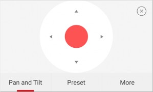

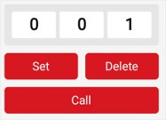


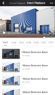


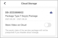
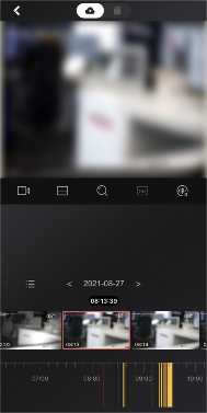
The Mobile Client allows you to browse through the video footage stored on cloud of each date to quickly locate the footage you need. And you can download the video footage to your phone.
![]()
Note
Make sure your installer has activate cloud storage service for your devices and you have enable it.
See details in Enable/Disable Cloud Storage Service for a Channel .
![]()
![]()
Note
1. Start playing back video footage stored on cloud.
See details in Play Back Video Footage on Cloud .
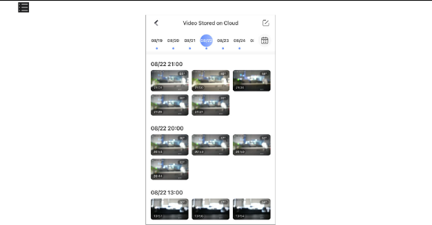
Tap to enter the Video Stored on Cloud page.
Figure 5-8 Video Stored on Cloud
![]()
Note
-
Select a date.
The date marked with a blue dot is the date during which video footage is recorded.

-
Tap , and then select the video footage you want to download.

-
Tap to download the selected video footage to your phone.
Chapter 6 Camera / NVR / DVR
The Mobile Client supports adding cameras, NVRs, and DVRs. After you add the devices, you can start live view, playback on the client. You can also link cameras with NVR/DVR, set motion detection alarms for network cameras, and reset password of NVRs or DVRs, etc.
-
-
Manage Solar Camera
After adding a solar camera to the Mobile Client, you can control and manage it remotely. The supported functions include waking up the device, viewing its network signal strength, switching power consumption mode, etc.
Unlike using other network cameras, you need to wake up a solar camera before you can control it. You can wake it up in the following two ways:
-
On the device list page, tap
to enter the device settings page. Once you enter this page, the camera will start waking up. -
On the device list, tap the device to enter its live view page. Once you enter this page, the camera will start waking up.
Enter the device settings page of the solar camera, and then tap Network Strength to view its network strength level.
Note
Enter the device settings page of the solar camera, tap Power Consumption Mode and then select a mode.
After switching power consumption mode, you need to reboot the solar camera to make the new settings take effect on the device.
-
-
Set Light for Floodlight Camera
You can set light for the Floodlight camera.
Make sure you have added a Floodlight camera to the Mobile Client.
-
On the device list page, tap to enter the Settings page of a Floodlight camera.
-
Tap Light Settings to enter the Light Settings page.
-
Set the parameters.
Adjust the brightness of the camera light.
If enabled, when activities of human beings or animals are detected at night in the areas specified by you (see Light Linkage Area Settings, the camera light will be automatically turned on.
Tap the areas to specify them as the light linkage areas.
-
-
Edit Settings of Cameras Linked to NVR/DVR
For cameras linked to NVR/DVR, you can edit their names, hide or show them in the device list, and enable camera cascading.
-
On the device list page, tap to enter the Settings page of a NVR or DVR.
-
Tap Linked Camera to enter the Linked Camera page, and then edit camera settings.
Hide/Show Camera
Tap to enter the camera details page, and then tap Channel Name to edit the camera name, and finally tap
to save the settings.
Tap or
 to hide or show the camera on the device list respectively.
 -
-
Set Motion Detection Alarm for Network Camera
Motion detection is a way of detecting motion in a surveillance scene by analyzing image data and differences in a series of images. After setting motion detection area within the field of view of the network camera, the network camera will be able to detect the objects in motion within the area you set and at the same the Mobile Client will receive an event notification about the motion detection alarm.
-
On the device list page, tap to enter the Settings page of the network camera.
-
Tap Notification to enter the Notification page.
-
Draw motion detection area.
-
Tap to go back to the Notification page and tap Motion Detection Sensitivity, and then adjust the slider to adjust the motion detection sensitivity.
Moving persons, large moving pets, and any other large moving objects in the motion detection area will trigger the alarm, while smaller objects will not.
Moving small pets and any other medium-sized moving objects in the motion detection area will trigger the alarm, while smaller objects will not.
Moving insects, moving leaves, and any other larger objects will trigger the alarm.
Note
Go back to the Notification page and make sure Notification is enabled.
For details about how to enabling notification, see Enable Event Notification
-
-
View Network Topology of NVR
Note
You can view network topology of the cameras connected to an NVR.
The NVR should support the network topology functionality.
On the device list page, tap
to enter the Settings page of the NVR, and then tap Network Camera Topology to enter the topology page. On the page, you can perform the following operations.On the topology, you can know the type of the network connection between each node (i.e., an NVR or a network camera) by the type of the line between the two nodes: solid line represents wired connection, dotted line Wi-Fi connection.
You can also view network status of the cameras. If a camera icon is grayed out, the camera is offline.
You can pinch fingers together to zoom in, and spread them apart to zoom out.
Tap
 in the upper right corner to refresh the topology structure.
Note
You can enable the topology to display a specific camera’s cascaded camera(s).
The NVR should support this function.
-
On the device list page, tap
to enter the Settings page of the device, and then tap Linked Camera to enter the Linked Camera page. -
Tap a camera on the Linked Camera page to enter the Details page.
-
Turn on Cascading Status to display cascaded camera(s) of a specific camera in the topology. Turn off to hide.
-
-
Reset Password of DVR or NVR via the Mobile Client
If you forgot the admin password of a DVR or NVR, you can reset the password by using the Mobile Client to scan the QR code generated on the local GUI of the device.
Two verification methods are provided for resetting the password of DVR or NVR: verifying by reserved email or verifying by Hik-Connect.
Procedures of Resetting Password via Hik-Connect Verification
It is recommended that you use this way to reset the password of DVR or NVR, which is comparatively simpler and more convenient. For details, see Reset Password by Hik-Connect .
Procedures of Resetting Password via Email Verification
The flow chart below shows the procedures of resetting password by email verification.

-
Reserve Email Address for Resetting Password: See Reserve Email Address for Resetting Password for details.
-
Generate QR Code on Device Local GUI (Verify by Reserved Email): See Generate QR Code by Reserved Email for details.
-
Reset Password of DVR or NVR by Scanning QR Code: See Reset Password by Reserved Email for details.
-
Reset Password by Hik-Connect
You can reset the password of DVR or NVR via Hik-Connect.
-
On the user login interface of the device, click Forgot Password.
-
On the password reset type interface, select Verify by Hik-Connect. The QR code will be generated on the local GUI of the device.
-
Go to the Hik-Connect Mobile Client, and then tap More → Reset Device Password to enter the
Reset Device Password page.
-
Scan the QR code.
A verification code will be displayed on the Mobile Client.
-
Go to the local GUI of the device and enter the received verification code, and then click OK to continue.
-
Create a new password and then confirm the password on the local GUI of the device.
-
-
Reserve Email Address for Resetting Password
Make sure you have reserved email address for resetting the admin password of NVR or DVR if you want to change the password by scanning QR code.
-
-
Upgrade the firmware of the NVR or DVR to make the device support self-service password reset.
-
If the device is inactivated, check Reserved Email Settings when activate it. For details about activating NVR or DVR, see the user manual of the device.
Note
The DVR or NVR should support the function.
-
Go to Configuration → User on the local GUI of the device.
-
Select admin user and then click Edit.
-
Enter the password of the device in the Old Password field.
-
Click the Settings icon in Reserved E-mail Settings field.
-
Enter an email address for receiving verification code, and then click OK.
-
Generate QR Code by Reserved Email
If you forgot the admin password of the DVR or NVR, you can generate a QR code on the device’s local GUI and then scan the QR code via the Mobile Client to reset the admin password.
Make sure you have reserved an email address for resetting password.
Note
The DVR or NVR should support this function.
-
On the login page of the device’s local GUI, click Forgot Password.
-
Select Verify by Reserved Email and then click OK.
-
Read and agree the Legal Disclaimer, and click OK to continue. The QR code for resetting password pops up.
-
-
-
-
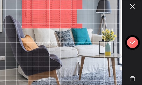
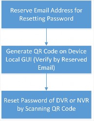
If you forgot the admin password of DVR or NVR, you can reset the password by scanning the QR code generated on the local GUI of the device.
-
Make sure you have allowed the Mobile Client to access your phone’s camera.
-
Make sure you have reserved email address for resetting device password and generated QR code on the device’s local GUI. For details, see Reserve Email Address for Resetting Password and Generate QR Code by Reserved Email for details.
-
Tap More → Reset Device Password to enter the Reset Device Password page.
-
Scan the QR code on the local GUI of the DVR or NVR.
Note
A verification code will be sent to the reserved email address.
-
The verification code will be valid for 48 hours.
-
If you reboot the device or change the reserved email address, the verification code would be invalid.
-
-
Go to the device’s local GUI.
-
Enter the received verification code on the Verify by Reserved Email window and then click OK
to reset the password.
Chapter 7 Access Control
Access control is the selective restriction of access to a place or other resources. After adding access control devices to the Mobile Client, you can remotely control the doors, and configure duration in which the doors remain open. You can also filter and view access control device’s logs, which provide the information of access events and related alarms, such as access controller tampering alarm.
Besides the above-mentioned functionality, you can change supper password of the access control device. And for face recognition terminals, you can enable fingerprint authentication or facial authentication to open doors.
-
-
Control Door Status
The Mobile Client supports controlling the status of the access control devices’ related doors by the super password of the device.
Add an access control device to the Mobile Client. See Add Device for Management for details.
Note
You can change the super password. See Change Super Password for details.

On the device list page, tap on the right of the access control device to enter the door
Note
control page.
The door icon varies with different door status.
-
Control the door status.
Keep the door open.
Note
Open the door for a configurable time period. When the time period expires, the door will close.
For details about configuring the time period, see Set Door Open Duration .
Note
Keep the door closed. In this status, the door can only be opened by super card or super password.
For details about super card, see the user manual of the access control device.
Note
-
Enter the super password.
-
For face recognition terminal, this step is not required. You can control door status directly in step 2.
-
By default, the super password is the device verification code. You can change the super password. See Change Super Password for details.
-
The door status will change.
-
-
Set Door Open Duration
You can set the door open duration for the access control device. When the duration expires, the door will close automatically.
Make sure you have added an access control device to the Mobile Client. See Add Device for Management for details.
-
On the device list page, tap to enter the Settings page of the access control device.
-
Tap Door Open Duration to open the Door Open Duration list.
-
Select a duration from the list.
-
Tap
to confirm the selection.
Note
If you tap Open Door in the door control page, the door will open for the configured time duration.
For details about controlling door status, see Control Door Status .
-
-
Change Super Password
The Mobile Client allows you to change the super password of the access control device, which can be used to open all the access control points (e.g., doors), even when the access control point is in remaining closed status.
Add an access control device to the Mobile Client. See Add Device for Management for details.
Note
For details about super password of the access control device, see the user manual of the device.
-
On the device list page, tap to enter the Settings page of the device.
-
Tap Change Password to enter the Change Password page.
Note
-
Enter the old password and tap Next.
If it is the first time to set the super password, skip this step.
Note
-
Create a new password and then tap Finish.
The password should contain 6 numbers.
-
-
View Access Control Logs
You can view the access control device’s logs including the access control events and alarm information. You can also filter the logs.
-
On the device list page, tap the door icon on the right of the access control device to enter the door control page.

Figure 7-1 The Icon Representing Door
The log list will be displayed on the Log section of the page.
-
Perform the following operations.
Refresh Log List Swipe the log list downward to refresh it.
View All Logs Tap View All Logs to enter the Log page and view all access control device logs.
Filter Logs On the Log page, tap Filter and then set the filtering condition (time and event type) to filter.
-
-
Enable Opening Door via Touch ID (or Face ID) Authentication
-
After adding face recognition terminals to the Mobile Client, you can enable opening door via Touch ID authentication or Face ID authentication.
Note
Your phone or tablet should support Touch ID authentication or Face ID authentication.
After adding a face recognition terminal, when you open the device’s related door for the first time, a prompt will pop up asking you whether to enable opening door via Touch ID authentication or Face ID authentication or not. You can follow the prompt to enable this function.
If you have ignored the above-mentioned prompt, you can tap to enter the Settings page, and then switch on the function.
Chapter 8 Security Control
The Mobile Client supports video security control panel, AX security control panel (including AX PRO, AX Hub, and AX Hybrid), and Pyronix security control panel.
A security control panel can be used to manage the devices needed in a security system, which can be used for detecting events (e.g., intrusion, smoke, water leakage, etc.,) within predefined regions (zones), triggering event signals and alarm signals, and uploading event information and alarms to the surveillance center.
-
-
AX PRO Security Control Panel
AX PRO security control panel is designed to protect premises required to be protected from intrusion. It supports LAN/Wi-Fi as the primary transmission network, and GRPS/3G/4G LTE as the secondary transmission network. It is applicable to the scenarios of market, store, house, factory, warehouse, office, etc.
-
-
-
Innovative Tri-X 2-way wireless technology.
-
Two-way communication with AES-128 encryption.
-
Frequently-hopping spread spectrum (FHSS) is used to avoid interference, to prevent eavesdropping, and to enable code-division multiple access (CDMA) communications.
-
Voice guide for alarm alert, system status indication, operation prompt, etc.
-
Configuration via device web page, Hik-Connect Mobile Client, and Hik-ProConnect Portal and Mobile Client.
-
Push alarm notifications via SMS or phone calls.
-
Uploads alarm reports to ARC.
-
SIA-DC09 protocol, and supports both Contract ID and SIA data format.
-
4520 mAh lithium backup battery with 12 H standby duration.
-
-
-
You can make the control panel connect to Wi-Fi via the Mobile Client.
-
On the device list page, tap the security control panel and then log in to the device to enter the page.
-
Follow the instructions on the page and change the control panel to the AP mode. Tap Next.
-
Select a stable Wi-Fi for the device to connect.
-
Back to configuration page to enter the Wi-Fi password and tap Next.
-
Tap Connect to a Network and wait for connection.
After the connection is completed, the control panel will prompt to exit AP mode and automatically switch to STA mode.
-
Optional: Tap Add Wi-Fi, enter SSID and Password, and select a security mode to manually add Wi-Fi when an AX PRO is not in the AP mode.
-
-
You can configure the cellular settings via the Mobile Client.
-
-
-
-
Make sure you have installed a SIM card in the device.
-
If you have granted an Installer with device authorization, cellular network configuration is available for the Installer only.
-
On the device list page, tap on the security control panel.
-
Optional: Turn on/off cellular network.
Note
-
Tap on the SIM card item.
You can set up for both SIM card slots for models with dual-SIM design.
-
Optional: Turn on Data Usage Limit to set an upper limit to avoid overage charges.
-
Tap Parameter Configuration to configure access number, APN, PIN, etc.
-
Optional: To check the balance of the SIM account, go back to the previous page and go to
Communication Parameters → Check Balance .
-
-
-
An area is a partition of a security control system that allows you to batch arm/disarm all zones in it. You can set area parameters such as area name, area background image, and auto arming/ disarming schedule.
Go to the settings page of the AX PRO and tap Area to see the area list of your AX PRO. By default, only Area 1 is enabled and cannot be disabled, and the rest are disabled.
Tap on an area to set the area parameters. See the descriptions of each parameter below.
Set a unique background for the area.


Note
Background images are stored on your Mobile Client only. Therefore, your background settings will not be shared among other users of the AX PRO.

Switch on to enable the area. When enabled, the area can be linked to zones and users.
Customize the name for the area.
Manage devices linked with an area of AxPro.
Set a schedule to automatically arm the area at a specific time.
Set a schedule to automatically disarm the area at a specific time.
Note
If Auto Arming Sound Prompt is enabled, the AX PRO will sound a prompt when armed automatically.
-
The system will not be compliant with the EN50131-1 standards when Auto Arming Sound Prompt is disabled.
-
This setting will take effect on all areas.
If Late to Disarm is enabled, the AX PRO will send a notification to remind you to disarm the area when the area is still armed after a specific time point.
Note
If Weekend Exception is enabled, Auto Arm, Auto Disarm, and Late to Disarm will be disabled on weekends.
You can set any day of a week as weekend.
Note
If Holiday Excepted is enabled, Auto Arm, Auto Disarm, and Late to Disarm will be disabled on holidays.
You can set the start date and end date of each holiday.
-
-
AX PRO offers different permissions for different user types. The Administrator can add, edit, and delete users, and assign different permissions to the newly-added users.
Note
-
-
-
-
There are four types of users in AX PRO, including Installer, Administrator, Operator, and Local User. Different types of users have different permissions for accessing the features of AX PRO.
Role
Permission
Installer
The installer has advanced configuration permissions*.
When the installer hands over the AX PRO to you, you will become the administrator of the device.
Administrator
The administrator has advanced configuration permissions* and full control permissions.
The administrator can share the AX PRO to invite other users to become the operators of the device. See details in Share a Device via Its QR Code .
Role
Permission
The operators’ permissions are controlled by the administrator.
The administrator can also add local users directly in User Management.
Operator
The operators have Limited configuration permissions and limited control permissions. The operators can use the Mobile Client to control the AX PRO.
Local User
The local users have no configuration permissions and limited control permissions. The local users can only use tags or keypads to control the AX PRO, such as arming or disarming the areas.
-
* If you have granted an installer with device authorization, advanced configurations are
available for the installer only. If device authorization is not granted to any installer, advanced configurations are available for the administrator of the device only.
-
On the device list page, tap the AX PRO.
-
Tap
→ User Management → User .
Figure 8-2 User Page
-
Optional: Perform further operations.
Check User ID AX PRO assigns a unique user ID to each user. When an alarm occurs, AX PRO will report the linked user ID along with other alarm information. If your Installer has enabled Alarm Receiving Center (ARC) service for the AX PRO, the alarm containing the user ID will be reported to ARC as well.

Note
For example, tenants in an apartment building co-use one AX PRO, and detectors (such as fire/smoke/CO/glass-break detectors) are set up for each room. The supervisor of the building needs to link each tenant’s account with the corresponding area, collect the room number, tenant contacts, and user ID in advance, and then provide these information to ARC. In case of emergency, whether detected by detectors or manually triggered by a tenant pressing a panic alarm (PA) button, an alarm including the related user ID will be reported to ARC. With such information, ARC can locate the alarm source in a targeted manner.

Tap the user to grant or cancel the permissions.
Note
Only the Administrator can control the permissions.
Tap the user and then tap Linked Areas to set the area linked to the target user.
Note
Only the Administrator can set linked areas.

Edit Duress Password
Tap the user and then tap Edit Keypad Password to set the keypad password of the target user.
Note
Tap the user and then tap Edit Duress Password to set the duress password of the target user.
If under duress, you can enter the duress code on the keyboard to arm and disarm area(s) and upload a duress alarm.
-
-
-
After adding cards/tags to the security control panel, you can swipe the card/tag to arm or disarm all the detectors added to specific area(s) of the security control panel, and clear alarms.
-
On the device list page, tap the security control panel and then log in to the device to enter the page.
-
Tap
→ User Management → Card/Tag to enter the Card/Tag Management page. -
Tap + to add a card/tag.
-
When hearing the voice prompt “Swipe Card”, you should present the card/tag on the control panel card presenting area.
-
When hearing a beep sound, the card/tag is recognized.
-
The card/tag will be displayed on the Card/Tag page.
-
-
Optional: Tap a Card/Tag to enter the Setting Page.
Note
-
Tap
to edit the card/tag name.The name should contain 1 to 32 characters.
-
Slide Enable Card/Tag..
-
Select a linked user.
Note
-
Select the card/tag type
Different linked users have different card/tag permissions.
You can swipe the tag/card to arm or disarm.
When you swipe the tag/card, the system will upload a record.
-
Optional: Tap Delete to delete the card/tag.
-
-
If you bypass a zone, the zone will NOT be armed (related alarms will not be triggered and faults will not be detected) even when the area is armed. Bypassing a zone is usually used in the following two scenarios: 1. If a zone is faulty, other zones of the same area can be armed only when the faulty zone is bypassed; 2. You want a specific zone not to trigger any alarms in special occasions.
On the Settings page of a zone (detector), turn on Zone Bypass to bypass it.
-
Arm/Disarm Areas and Clear Alarms
You can arm/disarm an area or clears the alarms in areas manually.
On the device list page, tap the security control panel to enter the Area page.

-
-
-
-
Stay Arm: Tap
to arm an area in Stay mode. When people need to stay inside the area, you can use Stay Arm to enable all the perimeter burglary detection (such as perimeter detectors, magnetic contacts, and curtain detectors). In the meantime, the indoor detectors inside the area are bypassed (such as indoor PIR detectors). People can move inside the area freely and the alarm will not be triggered. -
Away Arm: Tap
to arm an area in Away mode. You can activate Away Arm when you are leaving the area. The area will be armed after the last person exits the area and the exit delay time ends.
Note
-
Disarm: When the area is armed, you can tap
or again to disarm the area. In Disarm mode, no zone in the area will trigger any alarm even when alarm events are detected.24-Hour zones will trigger alarms whenever alarm events are detected, even if the area is disarmed.

Arm/Disarm Multiple Areas or Clear Alarms

Figure 8-4 Arming Control for All Areas

-
Away Arm: Tap to arm all areas in Away mode. You can activate Away Arm when you are leaving the premise. All areas will be armed after the last person exits the premise and the exit delay time ends.

-
Stay Arm: Tap to arm all areas in Stay mode. When people need to stay inside the premise, you can use Stay Arm to enable all the perimeter burglary detection (such as perimeter detectors, magnetic contacts, and curtain detectors). In the meantime, the indoor detectors inside the premise are bypassed (such as indoor PIR detectors). People can move inside the premise freely and the alarm will not be triggered.
Note
-
Disarm: Tap to disarm all areas. In Disarm mode, no zone will trigger any alarm even when alarm events are detected.
24-Hour zones will trigger alarms whenever alarm events are detected, even if the areas are disarmed.

-
Clear Alarm: Tap to clear all the alarms triggered by any zones.
Note

You can tap to select multiple areas. And then you can arm/disarm them or clear the alarms in these areas.

Figure 8-5 Select Areas
-
-
-
Virtual Panic Alarm (PA) Button
In case of emergency, you can tap the PA button for help. When you tap the PA button on the Mobile Client, the AX PRO will issue a panic alarm to alert the other users of the emergency. If the AX PRO has enabled with Alarm Receiving Center (ARC) service, the panic alarm will also be reported to the ARC.

Tap
and choose between audible panic alarm and silent panic alarm. After enabling panic alarm, the location will be included in the alarm information if the user has enabled the location service for the Mobile Client.
If your Installer has enabled ARC service for the AX PRO, the alarm containing location will be reported to ARC as well.
-
Note
The system fault list gathers the information on the errors and faults in the security control system in one place.
You can edit the system fault check items of the AX PRO. To edit them, go to the settings page of the AX PRO and tap System → System Options → System Fault Check .
You can tap on the AX PRO page to check the system fault list.

Figure 8-9 System Fault List
-
You can reboot the device.
-
On the device list page, tap the security control panel.
-
Tap
→ Maintenance . -
You can perform the following operations.
Operation Description
Reboot Device Tap Reboot Device to reboot the security control panel.
Device Upgrade Tap Device Upgrade to upgrade the device to a newer version.
Remote Log Collection a. Tap Remote Log Collection.
b. Enable Remote Log Collection.
Note
c. Set a valid time for the device.
Enable Remote Log Collection so that technical support personnel can collect device logs and troubleshoot problems remotely.
-
-
After you enable Find Me mode of a peripheral device, the indicator of the device will flash. In this way, you can easily distinguish a peripheral device from other devices.
Note
Enter the Settings page of the peripheral device, and then tap Find Me to start finding the device.
-
-
-
-
The function should be supported by the peripheral device.
-
Make sure that the security control panel is not armed, and that it is not under zone test mode, zone test mode, or signal strength test mode.
-
-
AX Hub Security Control Panel
Note
After adding an AX Hub security control panel to the Mobile Client, you can add wireless peripheral devices (including detectors, keyfobs, outputs expander, and siren) and cards/tags to the control panel. After that, you can control the alarm system by remotely arming or disarming areas via the Mobile Client, remotely pressing keys on keyfob, or swiping card.
-
-
-
AX Hub security control panel only supports wireless peripheral devices.
-
For details about how to add an AX security control panel to the Mobile Client, see Add Device(s) by Scanning Device QR Code or Add a Device by Hik-Connect Domain .
-
-
-
Log in to the Security Control Panel
Note
If the installer (or setter), which is a type of user of the security control panel, has enabled EN50131 Compliant mode, you should log in to the device before you can access the device.
For details about EN50131 Compliant mode, see EN50131 Compliant Mode .
On the device list page, tap the security control panel to enter the Verify Device page and then log in to the device.
-
Configure AX Security Control Panel
Note
On the Settings page of the security control panel, you can view and edit the basic information such as device name. You can also do configurations such as device time settings, area management, use management, etc.
There are four types of users, including administrator (or owner), operator, installer (or setter), and manufacturer. Different types of users have different permissions for the configuration of the security control panel. For details about the four types of users, see the user manual of the security control panel.
You can set system options such as system fault report, siren delay time, alarm duration, etc.
On the device list page, tap the security control panel and log in to the device (if required) to enter the Area page, and then tap
→ System Options to enter the System Options page.On the Option Management tab, you can do the following configurations.
If enabled, the system will detect the status of all wireless devices.
If enabled, the system will upload a report automatically when there is a system fault.
If enabled, all function keys will be disabled.
If enabled, the installer user can still operate the security control panel, while the admin user will not be allowed to operate it.
Siren Delay Time (Perimeter Alarm)
Note
The delay time to trigger the linked siren when a perimeter zone is triggered.
-
For details about perimeter zone, see the user manual of the security control panel.
-
The valid duration is from 0 s to 600 s.
Note
If you have set the perimeter zone, you can set the time duration of the alarm.
The valid duration is from 1 s to 900 s.
On the Fault Check tab, you can do the following configurations.
Detect Network Camera Disconnection
If enabled, when the linked network camera is disconnected, alarm will be triggered.
If enabled, when battery is disconnected or out of charge, the device will upload an event.
If enabled, when the wired network is disconnected or has other faults, alarm will be triggered.
If enabled, when the Wi-Fi is disconnected or has other faults, alarm will be triggered.
If enabled, when the cellular data network is disconnected or has other faults, alarm will be triggered.
If enabled, the alarm will be triggered when the SIM card has faults.
An alarm will be triggered if the AC power-down duration exceeds the configured time. To comply with the EN 50131-3 standards, set the value to 10 s.
You can enable specific area(s), and configure the public area.
Note
On the device list page, tap the security control panel and log in to the device (if required) to enter the Area page, and then tap
→ Area Management to enter the Area Management page.If EN50131 Compliant mode is enabled, you should log in to the security control panel before you can configure it. For details about enabling EN 50131 Compliant mode, see EN50131 Compliant Mode .
On the Enable Area tab, you can select area(s) to enable them. After the selected area(s) being enabled, you can do configurations such as linking zones to the area, delay time configuration, and weekend exception. For details, see Set Area Parameters .
On the Public Area Configuration tab, you can set the switch to on to set area 1 as the public area, and then set other areas (e.g., area 2 and area 3) as the areas linked to the public area.
-
-
-
-
-
Logic: Public area is a special area which can be shared with other areas. The public area is armed automatically when all areas linked with the public area are armed; And the public area is disarmed automatically when any one of areas linked with the public area is disarmed. The user can also arm or disarm the public area independently.
-
Usage Scenario: Public area is usually applied to manage or control a public area which is related with other areas controlled by other areas in one building.
The administrator and the installers can manage users. If you are the administrator, you can add, edit, and delete users, and assign different permissions to the newly-added users. If you are a installer, you can only add and delete users.
Note
There are four types of users for the security control panel, including administrator (or owner), operator, installer (or setter), and manufacturer. Different types of users have different permissions for accessing the functionality of the security control panel. For details, see the user manual of the security control panel.
Note
-
On the device list page, tap the security control panel and then log in to the device (if required) to enter the control panel page.
If EN50131 Compliant mode is enabled, you should log in to the security control panel first before you can configure the device. For details about enabling EN50131 mode, see EN50131 Compliant Mode .
-
Tap Add User.
-
Configure the required information.
Different user types have different permissions to access the functionality of the security control panel.
Note
For details, see the user manual of the security control panel.

Enter the user name.
Note
Create a password for the user.
We highly recommend you to create a strong password of your own choosing (using a minimum of 8 characters, including at least three kinds of following categories: upper case letters, lower case letters, numbers, and special characters) in order to increase the security of your product. And we recommend you change your password regularly, especially in the high security system, changing the password monthly or weekly can better protect your product.
Note
Create a password (4 to 6 characters) for the keypad.
The keypad password +1 or -1 is the duress code. If under duress, you can enter the duress code on the keyboard to arm and disarm area(s) and upload a duress alarm. For example, if the keypad password is 123456, the duress code is 123455 or 123457.
-
Tap Add to add the user.
-
Optional: Perform the following operations if required.
If you log in as an administrator, you can tap an installer, an operator, or a manufacturer on the user list, and then enable/disable the user on the user details page.

Note
If you log in as an installer, you can tap an operator or a manufacturer on the user list, and then enable/disable the user on the user details page.
Only the administrator and installer can enable/disable users.

Note
Set Linked Area If the target user is a an operator, tap the target user on the user list and then tap Area Linkage to set the area linked to the target user.
Only the administrator can do such an operation.
If the target user is a manufacturer, an installer, or an operator, you can tap the target user on the user list and then tap Permission to set the permissions authorized to the target user.
Note
Only the administrator can do such an operation.

Note
Delete User If the target user is an operator, tap the target user on the user list and then tap delete to delete the target user.
Only the administrator and installer can do such an operation.
You can add keyfobs to the security control panel to remotely control the area of the panel.
Note
-
On the device list page, tap the security control panel and then log in to the device (if required) to enter the area page.
If EN50131 Compliant mode is enabled, you should log in to the security control panel before you can configure it. For details about enabling EN 50131 Compliant mode, see EN50131 Compliant Mode .
-
Tap and then tap Add Keyfob on the Scan QR Code page.
-
Present the keyfob to the security control panel.
-
Press any button on the keyfob to learn.
Note
-
Create a keyfob name.
-
If you log in as an installer, skip this step.
-
The keyfob name should contain 1 to 32 characters.
Note
-
-
Select area(s) to be linked to the keyfob.
If you log in as an installer, skip this step. Selecting area is only available for the administrator.
You can remotely control the selected area(s) by the keyfob based on the permission(s) configured in step 8.
-
Set the Enable Keyfob switch to on to enable the keyfob.
Note
If you log in as an installer, skip this step. Enabling keyfob is only available for the administrator.
Note
-
Select permissions (such as the permission to disarm and clear alarm) for the keyfob to define what operations can be done via keyfob.
If you log in as an installer, skip this step. Setting permissions for keyfob is only available for administrator.
-
Tap Add.
-
Optional: Enable silent panic alarm.
1G) o to the settings page of the keyfob. 2E) nable Silent Panic Alarm.
When enabled, no linked alarm output (e.g., sound prompt) will be triggered when panic alarms of the keypad is triggered.
After adding cards or tags to the security control panel, you can swipe the card/tag to arm or disarm all the detectors added to specific area(s) of the security control panel, or clear alarms.
Note
1. On the device list page, tap the security control panel and then log in to the device (if required) to enter the area page.
If EN50131 Compliant mode is enabled, you should log in to the security control panel before you can configure it. For details about enabling EN 50131 Compliant mode, see EN50131 Compliant Mode .
Tap → User Management → Card/Tag Management → Add New Card/Tag to enter the
Card/Tag Management page.
-
When hearing the voice prompt “Swipe Card”, you should present the card/tag on the control panel card presenting area.
When hearing a beep sound, the card/tag is recognized.
Note
-
Create a card/tag name.
-
If you log in as an installer, skip this step. Editing card/tag name is only available to the the administrator.
-
The name should contain 1 to 32 characters.
The card/tag will be displayed on the Card/Tag Management page.
-
-
Select area(s) to be linked to the card/tag.
Note
If you log in as an installer, skip this step. Selecting area is only available for administrator.
You can remotely control the selected area(s) by the card/tag based on the permission(s) configured in step 7.
Note
-
Set the Enable Card/Tag switch to on to enable the card/tag.
If you log in as an installer, skip this step. Enabling card/tag is only available for the administrator.
Note
-
Select permissions (such as the permission to disarm and clear alarm) for the card/tag to define what operations can be done via card/tag.
If you log in as an installer, skip this step. Setting permissions for card/tag is only available for the administrator.
-
Tap Add.
Event video refers to the video cached when specific events occur. You can configure parameters (video channel, stream type, resolution, etc.) for the event video of the security control panel.
Note
On the device list page, tap the security control panel and then log in to the device (if required) to enter the control panel page.
If EN50131 Complaint mode is enabled, you should log in to security control panel first before you can configure the device. For details about enabling EN50131 Compliant mode, see EN50131 Compliant Mode .
Tap
 → Event Video Settings to enter the page, and then configure the following parameters.
Note
Set the channel for caching video.
You should have added network cameras to the security control panel. For details about adding network camera, see Add Network Camera Channel to Security Control Panel .
Used in recording and HD preview, it provides higher resolution, code rate and image quality.
Used to transmit network and preview pictures as a video streaming with features of lower resolution, bit rate and image quality.
A constant bitrate (hence the bandwidth) is used for the video regardless of the complexity of the video scenes. Increased activities in the video scenes will result in a poorer image quality because the restricted constant bitrate doesn’t reach the level to maintain sound image quality.
You can use constant bitrate when only limited network bandwidth is available.
A changeable bitrate (hence the bandwidth) is used for the video. The variability of bitrates allows videos to be recorded at a lower bitrate when there’s no motion in the video scene, and at a higher bitrate when there are a lot of activities.
It is recommended that you use variable bitrates when the network bandwidth is not limited and there is a need for high quality videos. Variable bitrates provide better image quality at the expense of a higher video storage requirements as the bitrate changes with the complexity of the video scenes.
Set the resolution for the video.
The higher the value is, the higher the video quality at the expense of higher bandwidth requirements.
Set the time point before the alarm to start caching video.
Set the time point after the alarm to stop caching video.
Configure Push Notification Settings for AX Security Control Panel
You can set a phone number to allow the security control panel to call the phone number or send SMS messages to the phone number when specific alarms (events) are triggered.
1. On the device list page, tap the security control panel and log in to the device (if required) to enter the Area page.
Note
If EN50131 Compliant mode is enabled, you should log in to the security control panel first before you can configure the device. For details about enabling EN50131 Compliant mode, see EN50131 Compliant Mode .
Tap → Communication Parameters → Push Notification(s) .
-
Tap Add Phone Number to enter a phone number.
-
Allow the security control panel to call the phone number or send SMS messages to the phone number when specific alarms (events) are triggered.
-
Tap Phone Call.
-
Set the Phone Call switch to on.
-
Tap Numbers of Calling to set the maximum calling times if the call is not accepted.
-
Select the event(s) for triggering the phone call.
Set a time interval for avoid receiving excessive notifications about the same event (alarm) type within a short period of time.
If the alarm is triggered for more than one time within the configured time interval, the alarm is considered as only being triggered for one time.
SMS a. Tap SMS.
-
Set SMS switch to on.
-
Select the event(s) for triggering the SMS notification.

Note
-
In the Permission Settings section, select the area(s) that you (installer) have permissions to arm, disarm, and clear alarm via sending control messages to the number of the SIM card installed in the security control panel.
-
-
For details about control messages, see Table 8-2 below.

After receiving the phone calls or SMS messages about the alarms (events), you can use your phone to send a control messages to arm/disarm the selected area(s) or clear alarm for the area(s) you selected on the Permission Settings page of the SMS tab.
The control message is Command + Operation + Target, and the details are shown below.
Table 8-2 Control Message Description
Command
Operation Type
Target
The number representing the command should be 2 digits.
00: Disarm
The number representing the operation type should be 1 digit.
The number representing the target area should be no more than 3 digits.
01: Away
1: Area Operation
0: All Areas
02: Stay
1: Area 1
Command
Operation Type
Target
03: Clear Alarm
…
4: Area 4
For example, the control message which reads 00+1+1 means to disarm area 1; And 01+1+1
means to set the status of area 1 to Away.
You can enable EN50131 Compliant mode to make the security control panel be compliant with the EN50131 standards.
On the device list page, tap the security control panel and log in to the device (if required) to enter the Area page, and then tap
to enter the Settings page to set the EN50131 Compliant switch to on.Caution
After enabling the mode, the adding user functionality will be available, and all users of the security control panel should log in to the device by user name and device password before they can access the device.
Note
If the mode is disabled, the security control panel will NOT be compliant with EN 50131 standard. Please contact the after sales or our technical support for information about the risks that may be incurred in your country if you disable the mode.
Only the Installer (or Setter) has the permission to enable/disable EN50131 Compliant mode.
You can do other settings including setting time zone for the security control panel (hereafter simplified as device), configuring device network, enabling Arming Process to auto detect the device faults during arming process, etc.
Note
On the device list page, tap the security control panel and log in to the device (if required) to enter the Area page, and then tap
to enter the Settings page.If EN50131 Compliant mode is enabled, you should log in to the security control panel first before you can configure the device. For details about enabling EN501313 Compliant mode, see EN50131 Compliant Mode .
View device information such as device model, battery level, and Wi-Fi status; And set time zone and enable Daylight Saving Time (DST) for the device.
Note
Reboot the device or partly restore the device.
If the device is partly restored, the device will restore to its default settings except for admin parameters, wired network parameters, Wi-Fi parameters, detector parameters, and wireless device parameters.
Follow the instructions to configure network for the device.
Cellular Data Network Settings
Tap Communication Parameters → Cellular Data Network Settings to configure the related parameters.
If disabled, the device will not be available to use in mobile network.
You can set the phone number, user name, access password, MTU, etc.
Ask the network carrier the access password and then enter it.
Ask the network carrier to get the APN information and then enter the APN information.
If enabled, the cellular data usage of the security control panel per month will be limited. You can view the data used in the current month, and set the limit per month.
Set the Enable Arming Process switch to on to enable the mode.
After enabled, the device will automatically detect its fault(s) during the arming process. You can determine whether to continue arming or not if fault(s) are detected.
-
-
-
Add Device to the Security Control Panel
You should add detectors (zones), peripheral devices, keyfobs, cards/tags to the panel before you can perform further operations such as arming and disarming. The peripheral devices include wireless outputs expanders, and sirens, etc.
Add Peripheral Device by Scanning QR Code
You can add wireless peripheral devices to the panel by scanning the device QR code.
-
On the device list page, tap the security control panel and then log in to the device (if required) to enter the Area page.
-
Add a peripheral device.
-
Tap Zone →
to enter the Scan QR Code page to add a detector. -
Tap Peripheral Device →
to enter the Scan QR Code page to add other types of peripheral devices.Note
-
-
Scan the QR code of the device.
The QR code is usually on the back cover of the device.
Note
-
Optional: If the QR code fails to be recognized, tap and enter the serial number of the device, and then select the device type.
The serial number is usually on the back cover of the device.
Note
-
For AX Hybrid, tap Select Wireless Receiver to select a wireless receiver.
For AX Hub, skip this step.
-
Tap Add.
-
Optional: Tap the device on the zone list or the peripheral device list to enter the Settings page and then tap Delete to delete the device.
Add Network Camera Channel to Security Control Panel
You can add network cameras to the security control panel as the video channel for the security control panel.
-
On the device list page, tap the security control panel and then log in to the device (if required) to enter the control panel page.
Note
If EN50131 Compliant mode is enabled, you should log in to the security control panel first before you can configure the device.
-
Tap → Network Camera Channel to enter the Network Camera Channel page.
-
Tap the + icon or Add Channel to enter the Add Channel page.
-
Set the required information, including IP address, protocol type, port, user name, and password.
-
Tap
to add the channel. -
Optional: Perform the following operations if required.
Edit a Channel Select a channel from the channel list, and then tap
to edit it,such as IP address and user name.Delete a Channel Select a channel from the channel list, and then tap Delete to delete it.
-
-
The Mobile Client allows you to set area parameters such as alarm duration, auto arm, and auto disarm. A area is an independent control system of a security control panel. It allows you to batch arm/disarm all zones in it. If the security control panel has two areas, you have two independent systems for arming or disarming.
Note
-
On the device list, tap the security control panel and then log in to the device (if required) to enter the Area page.
If EN50131 Compliant mode is enabled, you should log in to the security control panel first before you can configure the device. For details about enabling EN50131 Compliant mode, see EN50131 Compliant Mode .
-
Tap More to enter the Settings page.
-
Configure parameters for the area.
Enable the area to automatically arm itself in a specific time point.
Set the time point for the area to automatically arm itself.
Enable the device to push a notification to the phone or tablet to remind the user to disarm the area when the area is still armed after a specific time point.
Note
Make sure you have enabled Operation Event Notification on the web page of the security control panel, or the notification will not be pushed to the phone or tablet. For details about the web page, see the user manual of the security control panel.
Set the time point mentioned in Late to Disarm.
If enabled, Auto Arm, Auto Disarm, and Late to Disarm will be disabled on the weekend.
Entry Delay 2
Set a value for Entry Delay 1 and Entry Delay 2. Entry delay is a time concept. If entry delay is configured for the delayed zone, when you enter an armed delayed zone, the zone alarm will not be triggered until the end of entry delay.
Note
Entry delay is usually used for avoiding the triggering of false alarms when you enter a certain armed region. For example, you can set an entry delay after you arm your home. In this way, you can avoid the unnecessary triggering of intrusion alarm between the time point when you return home and the time point when you finally disarm your home.
After set value for Entry Delay 1 and Entry Delay 2, you should set the entry delay of a specific zone to the value of Entry Delay 1 or Entry Delay 2. see Set Zone Parameters for details.
Set exit delay for the delayed zone. If exit delay is configured for the delayed zone, after you arm the zone on the indoor unit, you can exit the zone without triggering alarm until the end of exit delay.
Exit delay is usually used for avoiding the triggering of false alarms when you exit a certain armed region. For example, you can set an exit delay after you arm your home. In this way, you can avoid the unnecessary triggering of intrusion alarm between the time point when you arm your home and the time point when you exit your home.
-
-
You can set arming mode and clear alarms for areas of the security control panel via the Mobile Client. Area, which is an independent control system of a security control panel, allows you to batch arm/disarm all zones in it. If the security control panel has multiple areas, you have multiple independent systems for arming or disarming.
On the device list page, tap the security control panel and then log in to the device (if required) to enter the Area page and then control the area. You can swipe to the left or right to switch areas.
Note
-
-
-
-
If EN50131 Compliant mode is enabled, you should log in to the security control panel first before you can configure the device. For details about enabling EN50131 Compliant mode, see EN50131 Compliant Mode .
-
You can also tap the arming status icon on the device list to arm or disarm the area(s).
-
If EN50131 Compliant mode is enabled for the device, controlling area(s) is not available by tapping the arming status icons.
-
Away: When all the people in the detection area leave, turn on the Away mode to arm all zones in the area after the defined dwell time. For example, assume that you have set your apartment as a zone, you can set the zone status to Away when you go to work.
-
Stay: When the people stays inside the detection area, turn on the Stay mode to turn on all the perimeter burglary detection (such as perimeter detector, magnetic contacts, curtain detector in the balcony). At the meantime, the detectors inside the detection area are bypassed (such as PIR detectors). People can move inside the area and alarm will not be triggered.
-
Disarm: In Disarm mode, all the zones in the area will not trigger alarm, no matter the selected events are detected or not.
-
Clear Alarm: Clear all the alarms triggered by the zones of the area.
-
Away: When all the people in the detection area leave, turn on the Away mode to arm all zones in all areas after the defined dwell time.
-
Stay: When the people stays inside the detection area, turn on the Stay mode to turn on all the perimeter burglary detection (such as perimeter detector, magnetic contacts, curtain detector in the balcony) set in all the zones of all areas. At the meantime, the detectors inside the detection area are bypassed (such as PIR detectors). People can move inside the area and alarm will not be triggered.
-
Disarm: In Disarm mode, all the zones of all areas will not trigger alarm, no matter the selected events are detected or not.
-
Clear Alarm: Clear all the alarms triggered by the all the zones of all the areas.
-
-
-
You can set zone parameters, such as zone type, linked camera, and Stay/Away settings. Zone is a basic concept in the security control panel system. It refers to a protection area in the system, and is regarded as the maximum recognizable unit to distinguish the alarm event.
Make sure you have linked detector(s) to the security control panel. For details, see the user manual of the security control panel.
Note
-
On the device list page, tap the security control panel and then log in to the device (if required) to enter the control panel page.
If EN50131 Compliant mode is enabled, you should log in to the security control panel before you can configure the device. For details about enabling EN50131 Compliant mode, see EN50131 Compliant Mode .
-
Tap Zone and then tap a detector (zone) on the zone list to enter the Settings page.
-
Set parameters for the zone (or detector).
See the descriptions of each zone type on the Zone Type page.
Note
If you select Delayed Zone, you should select an entry delay (Entry Delay 1 or Entry Delay 2) on the pop-up page.
You can set Entry Delay 1 and Entry Delay 2. See Set Area Parameters for details.
If you select Timeout Zone, you should select a timeout value or tap Custom to set a custom value.
Link a camera to the zone. See Link Camera to Zone for details.
Note
If enabled, the zone will be auto-bypassed during stay arming.
For details about bypassing a zone, see Bypass a Zone .
Enable the security control panel to chime when the zone is triggered.
If enabled, the detector only alarm when it is triggered for two times within the time interval (i.e., Double Knock Time Interval) you set.
This is useful for avoiding false alarms.
If enabled, no siren will be triggered if alarm occurs.
-
-
If you bypass a zone, the zone will NOT be in alert condition (related alarms will not be triggered and related faults will not be detected) even when the system (or area) which it belongs to is armed. Bypassing a zone is usually used in the following two scenarios. The first is that if a zone is faulty, other zones of the same system (or area) can be armed only when the faulty zone is bypassed. The second is that you simply want a specific zone NOT to trigger alarms in special occasions.
Note
On the Settings page of a detector (or zone), turn on Zone Bypass to bypass the detector (or zone).
For details about how to enter the Settings page of a detector (or zone), see Set Zone Parameters .
-
If a network camera has already been linked to the security control panel, you can link the camera to a zone managed by the control panel via the Mobile Client. After that, you can view the zone’s alarm-related video when receiving the zone’s alarm notification. You can also link a network camera added to the Mobile Client to a zone managed by the control panel, so as to view the zone’s live video and play back the zone’s videos.
-
-
-
-
Make sure you have mounted the network camera in the zone. See the user manual of the network camera for details.
-
To view the alarm-related video when receiving zone’s alarm notification, make sure you have linked the network camera to the security control panel via the panel’s Web Client. For details, see the user manual of the AX wireless security control panel.
Note
The zone’s alarm-related video lasts 7 seconds (from 5 seconds before the alarm to 2 seconds after the alarm).
Note
-
On the device list page, tap the security control panel and then log in to the device (if required) to enter the Area page.
If EN50131 Compliant mode is enabled, you should log in to the security control panel first before you can configure the device. For details about enabling EN50131 Compliant mode, see EN50131 Compliant Mode .
-
Tap Zone and then select a detector from the zone list.
-
Tap Link Camera to enter the Link Camera page.


4.
Drag a camera from the Available Cameras section to
5. Tap Link .
-
-
-
Set Parameters of Wireless Outputs Expander
You can set the alarm output type and the output delay for the relays of a wireless outputs expander. Alarm output is the node signal or other signal sent from the alarm controller to the peripheral devices when the alarm is triggered.
Make sure you have added wireless outputs expander(s) to the security control panel.
Note
-
On the device list page, tap the security control panel and then log in to the device (if required) to enter the Area page.
If EN50131 Compliant mode is enabled, you should log in to the security control panel first before you can configure the device. For details about enabling EN50131 Compliant mode, see EN50131 Compliant Mode .
-
Tap Peripheral Device and then tap a wireless outputs expander on the device list. The name of the module and the relays of the expander will be displayed.
-
Click the name of the module to set its parameter.
Note
If the time during which the wireless outputs expander loses communication with the security control panel exceeds the configured offline duration, the wireless outputs expander will be regarded as offline.
The default offline duration is 1 hour.
-
Tap a relay to enter its settings page to set its parameters.
If enabled, the relay will be normally closed or open.
The delay time for the relay to become closed. In other words, output delay refers to the duration of the alarm output.
Set the type of the event linked to the relay.
Alarm outputs will be activated when the zones in the selected area(s) alarm.
You can select a event sub-type (e.g, panic alarm) as the event that requires alarm output once it is detected within the zones.
Alarm outputs will be activated when the area(s) you select are armed.
Alarm outputs will be activated when the selected area(s) are disarmed.
Set the switch icon to ON to manually activate alarm outputs of the relay.
Alarm outputs will be activated when the selected zone(s) are triggered or tampered.
-
-
Set Wireless Siren Parameters
You can edit the name of the wireless siren and set the siren’s volume.
Make sure you have added wireless siren(s) to the security control panel. For details, see Add Device to the Security Control Panel .
Note
-
On the device list page, tap the security control panel and then log in to the device (if required) to enter the Area page.
If EN50131 Compliant mode is enabled, you should log in to the security control panel first before you can configure the device. For details about enabling EN50131 Compliant mode, see EN50131 Compliant Mode .
-
Tap Peripheral Device and then tap a siren on the device list to enter the siren settings page.
-
Perform the following operations.
Edit Siren Name Tap the siren name to edit it, and then tap
.
Note
Set Siren Volume Drag the slider to set the volume.
The function should be supported by the siren.

-
Set parameters.
If the time during which the siren loses communication with the security control panel exceeds the configured offline duration, the siren will be regarded as offline.
Note
If enabled, the LED indicator of the siren will flash for one time when a area is armed, two times when disarmed.
For sirens of the versions earlier than V1.0.6, the parameter is not supported.
Note
If enabled, the buzzer of siren will buzz for one time when a area is armed, two times when disarmed.
For sirens of the versions earlier than V1.0.6, the parameter is not supported.
Note
Tap to test the volume of the siren.
For sirens of the versions earlier than V1.0.6, the parameter is not supported.
-
-
Set Wireless Keypad Parameters
You can set the wireless keypad parameters, including device name, buzzer, card/tag swiping, backlight, and security settings, etc.
Make sure you have added wireless keypad to the security control panel.
Note
-
On the device list page, tap the security control panel and then log in to the device (if required) to enter the Area page.
If EN50131 Compliant mode is enabled, you should log in to the security control panel first before you can configure the device. For details about enabling EN50131 Compliant mode, see EN50131 Compliant Mode .
-
Tap Peripheral Device and then tap a wireless keypad on the device list.
-
Set the parameters.
Set the area linked to the keypad. The linked area can be arm/disarm or clear alarm by the keypad.
Enable the buzzer.
Enable swiping card/tag on the keypad to arm/disarm the linked area or clear alarms.
Enable using keypad to arm/disarm the linked area or clear alarms.
Enable the backlight of the keypad.
If the time during which the keypad loses communication with the security control panel exceeds the configured offline duration, the keypad will be regarded as offline.
When enabled, no linked alarm output (e.g., sound prompt) will be triggered when panic alarms of the keypad is triggered.
Security Settings Locked Duration
Specify the duration that the keypad remains locked if the failed keypad password attempts reach the specified maximum times.
Specify the maximum failed attempts for entering the incorrect keypad password consecutively. If the failure times reaches the specified value, the keypad will remain locked for a specified duration.
-
-
Set Wireless Card/Tag Reader Parameters
You can set the wireless card/tag reader parameters, including device name, linked area, buzzer, offline duration, and security settings.
Make sure you have added wireless card/tag readers to the security control panel.
Note
-
On the device list page, tap the security control panel and then log in to the device (if required) to enter the Area page.
If EN50131 Compliant mode is enabled, you should log in to the security control panel first before you can configure the device. For details about enabling EN50131 Compliant mode, see EN50131 Compliant Mode .
-
Tap Peripheral Device and then tap a wireless keypad on the device list.
-
Set the parameters.
Set the area linked to the wireless card/tag reader. The linked area can be arm/disarm or clear alarm by swiping card/tag on the card/tag reader.
Enable the buzzer of the card/tag reader.
If the time during which the siren loses communication with the security control panel exceeds the configured offline duration, the siren will be regarded as offline.
Security Settings Locked Duration
Specify the duration that the card/tag reader remains locked if the failed card/tag swiping attempts reach the specified maximum times.
Specify the maximum failed attempts for swiping card/tag. If the failure times reaches the specified value, the card/tag reader will remain locked for a specified duration.
-
-
-
AX Hybrid Security Control Panel
Note
Compared with AX Hub security control panel, AX Hybrid security control panel supports not only wireless peripheral devices, but also wired ones. After adding an AX Hybrid security control panel to the Mobile Client, you can add peripheral devices (including detectors, keyfobs, outputs expander, and siren) and cards/tags to the control panel. After that, you can control the alarm system by remotely arming or disarming areas via the Mobile Client, remotely pressing keys on keyfob, or swiping card.
For details about how to add an AX Hybrid security control panel to the Mobile Client, see Add Device(s) by Scanning Device QR Code or Add a Device by Hik-Connect Domain .
-
Configure Security Control Panel
Note
On the Settings page of the security control panel, you can view and edit the basic information such as device name. You can also do configurations such as device time settings, area management, use management, etc.
There are four types of users, including administrator (or owner), operator, installer (or setter), and manufacturer. Different types of users have different permissions for the configuration of the security control panel. For details about the four types of users, see the user manual of the security control panel.
You can set system options such as system fault report, siren delay time, alarm duration, etc.
On the device list page, tap the security control panel and log in to the device to enter the Area page, and then tap
→ System Options to enter the System Options page.On the Option Management tab, you can do the following configurations.
If enabled, the system will detect the status of all wireless devices.
If enabled, the system will upload a report automatically when there is a system fault.
If enabled, all function keys will be disabled.
Siren Delay Time (Perimeter Alarm)
Note
The delay time to trigger the linked siren when a perimeter zone is triggered.
-
For details about perimeter zone, see the user manual of the security control panel.
-
The valid duration is from 0 s to 600 s.
Note
If you have set the perimeter zone, you can set the time duration of the alarm.
The valid duration is from 1 s to 900 s.
On the Fault Check tab, you can do the following configurations.
Detect Network Camera Disconnection
If enabled, when the linked network camera is disconnected, alarm will be triggered.
If enabled, when battery is disconnected or out of charge, the device will upload an event.
If enabled, when the wired network is disconnected or has other faults, alarm will be triggered.
If enabled, when the Wi-Fi is disconnected or has other faults, alarm will be triggered.
If enabled, when the cellular data network is disconnected or has other faults, alarm will be triggered.
If enabled, the alarm will be triggered when the SIM card has faults.
An alarm will be triggered if the AC power-down duration exceeds the configured time. To comply with the EN 50131-3 standards, set the value to 10 s.
You can enable specific area(s), and configure the public area.
On the device list page, tap the security control panel and log in to the device (if required) to enter the Area page, and then tap → Area Management to enter the Area Management page.
On the Enable Area tab, you can select area(s) to enable them. After the selected area(s) being enabled, you can do configurations such as linking zones to the area, delay time configuration, and weekend exception. For details, see Set Area Parameters .
On the Public Area Configuration tab, you can set the switch to on to set area 1 as the public area, and then set other areas (e.g., area 2 and area 3) as the areas linked to the public area.
-
-
-
-
-
Logic: Public area is a special area which can be shared with other areas. The public area is armed automatically when all areas linked with the public area are armed; And the public area is disarmed automatically when any one of areas linked with the public area is disarmed. The user can also arm or disarm the public area independently.
-
Usage Scenario: Public area is usually applied to manage or control a public area which is related with other areas controlled by other areas in one building.
The administrator and the installers can manage users. If you are the administrator, you can add, edit, and delete users, and assign different permissions to the newly-added users. If you are a installer, you can only add and delete users.
Note
There are four types of users for the security control panel, including administrator (or owner), operator, installer (or setter), and manufacturer. Different types of users have different permissions for accessing the functionality of the security control panel. For details, see the user manual of the security control panel.
-
On the device list page, tap the security control panel and then log in to the device to enter the control panel page.
-
Tap
 → User Management → User .
Figure 8-11 User Management
-
Tap Add User.

-
Select User Type. Enter User Name and Password.
Note
-
Enter Keypad Password.
The keypad password +1 or -1 is the duress code. Use the duress code can operate the keyboard to arm and disarm normally and upload a duress alarm. For example, if the keypad password is 123456, the duress code is 123455 or 123457.
-
Tap Add to add the user.
-
Optional: Perform the following operations if required.
If you log in as an administrator, you can tap an installer, an operator, or a manufacturer on the user list, and then enable/disable the user on the user details page.
Note
If you log in as an installer, you can tap an operator or a manufacturer on the user list, and then enable/disable the user on the user details page.
Only the administrator and installer can enable/disable users.
Note
Set Linked Area If the target user is a an operator, tap the target user on the user list and then tap Area Linkage to set the area linked to the target user.
Only the administrator can do such an operation.
If the target user is a manufacturer, an installer, or an operator, you can tap the target user on the user list and then tap Permission to set the permissions authorized to the target user.
Note
Only the administrator can do such an operation.
Note
Delete User If the target user is an operator, tap the target user on the user list and then tap delete to delete the target user.
Only the administrator and installer can do such an operation.
You can add keyfobs to the security control panel to remotely control the area of the panel.
-
On the device list page, tap the security control panel and then log in to the device to enter the area page.
-
Tap
→ User Management → Keyfob Management → Add New Keyfob to enter the Card/Tag Management page. -
Select a wireless receiver or keypad.
-
Present the keyfob to the wireless receiver or keypad.
-
Press any button on the keyfob to learn.
Note
-
Create a keyfob name.
-
If you log in as an installer, skip this step.
-
The keyfob name should contain 1 to 32 characters.
Note
-
-
Select area(s) to be linked to the keyfob.
If you log in as an installer, skip this step. Selecting area is only available for the administrator.
You can remotely control the selected area(s) by the keyfob based on the permission(s) configured in step 9.
Note
-
Set the Enable Keyfob switch to on to enable the keyfob.
If you log in as an installer, skip this step. Enabling keyfob is only available for the administrator.
-
Select permissions (such as the permission to disarm and clear alarm) for the keyfob to define what operations can be done via keyfob.
Note
If you log in as an installer, skip this step. Setting permissions for keyfob is only available for the administrator.
-
Tap Add.
-
Optional: Enable silent panic alarm.
1G) o to the settings page of the keyfob. 2E) nable Silent Panic Alarm.
When enabled, no linked alarm output (e.g., sound prompt) will be triggered when panic alarms of the keypad is triggered.
After adding cards or tags to the security control panel, you can swipe the card/tag to arm or disarm all the detectors added to specific area(s) of the security control panel, or clear alarms.
-
On the device list page, tap the security control panel and then log in to the device (if required) to enter the area page.
-
Tap
→ User Management → Card/Tag Management → Add New Card/Tag to enter the Card/Tag Management page. -
Select a keypad.
-
When hearing the voice prompt “Swipe Card”, you should present the card/tag on the control panel card presenting area.
When hearing a beep sound, the card/tag is recognized.
Note
-
Create a card/tag name.
-
If you log in as an installer, skip this step. Editing card/tag name is only available to the administrator.
-
The name should contain 1 to 32 characters.
The card/tag will be displayed on the Card/Tag Management page.
Note
-
-
Select area(s) to be linked to the card/tag.
If you log in as an installer, skip this step. Selecting area is only available for the administrator.
You can remotely control the selected area(s) by the card/tag based on the permission(s) configured in step 8.
-
Set the Enable Card/Tag switch to on to enable the card/tag.
Note
If you log in as an installer, skip this step. Enabling card/tag is only available for the administrator.
Note
-
Select permissions (such as the permission to disarm and clear alarm) for the card/tag to define what operations can be done via card/tag.
If you log in as an installer, skip this step. Setting permissions for card/tag is only available for the administrator.
-
Tap Add.
Event video refers to the video cached when specific events occur. You can configure parameters (video channel, stream type, resolution, etc.) for the event video of the security control panel.
On the device list page, tap the security control panel and then log in to the device to enter the control panel page.
Tap
→ Event Video Settings to enter the page, and then configure the following parameters.Note
Set the channel for caching video.
Make sure you have added network cameras to the security control panel. For details about adding network camera, see Add Network Camera Channel to Security Control Panel .
Used in recording and HD preview, it provides higher resolution, code rate and image quality.
Used to transmit network and preview pictures as a video streaming with features of lower resolution, bit rate and image quality.
A constant bitrate (hence the bandwidth) is used for the video regardless of the complexity of the video scenes. Increased activities in the video scenes will result in a poorer image quality because the restricted constant bitrate doesn’t reach the level to maintain sound image quality.
You can use constant bitrate when only limited network bandwidth is available.
A changeable bitrate (hence the bandwidth) is used for the video. The variability of bitrates allows videos to be recorded at a lower bitrate when there’s no motion in the video scene, and at a higher bitrate when there are a lot of activities.
It is recommended that you use variable bitrates when the network bandwidth is not limited and there is a need for high quality videos. Variable bitrates provide better image quality at the expense of a higher video storage requirements as the bitrate changes with the complexity of the video scenes.
Set the resolution for the video.
The higher the value is, the higher the video quality at the expense of higher bandwidth requirements.
Set the time point before the alarm to start caching video.
Set the time point after the alarm to stop caching video.
Configure Push Notification Settings for AX Security Control Panel
You can set a phone number to allow the security control panel to call the phone number or send SMS messages to the phone number when specific alarms (events) are triggered.
-
On the device list page, tap the security control panel and log in to the device to enter the Area page.
-
Tap Add Phone Number to enter a phone number.
-
Allow the security control panel to call the phone number or send SMS messages to the phone number when specific alarms (events) are triggered.
-
Tap Phone Call.
-
Set the Phone Call switch to on.
-
Tap Numbers of Calling to set the maximum calling times if the call is not accepted.
-
Select the event(s) for triggering the phone call.
Set a time interval for avoid receiving excessive notifications about the same event (alarm) type within a short period of time.
If the alarm is triggered for more than one time within the configured time interval, the alarm is considered as only being triggered for one time.
SMS a. Tap SMS.
-
Set SMS switch to on.
-
Select the event(s) for triggering the SMS notification.
Note
-
In the Permission Settings section, select the area(s) that you (installer) have permissions to arm, disarm, and clear alarm via sending control messages to the number of the SIM card installed in the security control panel.
-
-
For details about control messages, see Table 8-2 below.

After receiving the phone calls or SMS messages about the alarms (events), you can use your phone to send a control messages to arm/disarm the selected area(s) or clear alarm for the area(s) you selected on the Permission Settings page of the SMS tab.
The control message is Command + Operation + Target, and the details are shown below.
Table 8-3 Control Message Description
Command
Operation Type
Target
The number representing the command should be 2 digits.
00: Disarm
The number representing the operation type should be 1 digit.
The number representing the target area should be no more than 3 digits.
01: Away
1: Area Operation
0: All Areas
02: Stay
1: Area 1
03: Clear Alarm
…
4: Area 4
For example, the control message which reads 00+1+1 means to disarm area 1; And 01+1+1
means to set the status of area 1 to Away.
-
-
-
Add Device to Security Control Panel
You should add detectors (zones), other peripheral devices, keyfobs, cards/tags to the panel before you can perform further operations such as arming and disarming. The peripheral devices include wireless outputs expanders, sirens, keypad, etc.
Add Peripheral Device by Scanning QR Code
You can add peripheral devices to the panel by scanning the device QR code.
-
On the device list page, tap the security control panel and then log in to the device (if required) to enter the Area page.
-
Add a peripheral device.
-
Tap Zone →
to enter the Scan QR Code page to add a detector. -
Tap Peripheral Device →
to enter the Scan QR Code page to add other types of peripheral devices.
Note
-
-
Scan the QR code of the device.
The QR code is usually on the back cover of the device.
Note
-
Optional: If the QR code fails to be recognized, tap and enter the serial number of the device, and then select the device type.
The serial number is usually on the back cover of the device.
-
Tap Select Wireless Receiver to select a wireless receiver.
-
Tap Add.
-
Optional: Tap the device on the zone list or the peripheral device list to enter the Settings page and then tap Delete to delete the device.
Add Peripheral Device in Enrollment Mode
In Enrollment mode, when you bring the peripheral device (or detector) close to a wireless receiver, wireless communication between them will be established after you confirm such an establishment. And at the same time through the wired connection between the security control panel and the wireless receiver, which plays the role of intermediary, the connection between the peripheral device (or detector) and the security control panel will be established.
Make sure you have added wireless receiver(s) or keypad to the AX Hybrid security control panel. For details, see the user manual of the device.
-
On the device list page, tap the security control panel and then log in to the device (if required) to enter the Area page.
-
Tap
to enter the Settings page. -
Tap Enrollment Mode to enter the Device Type page.
The Device Type page displays four device types, including detector, wireless output expander, and wireless siren.
-
Select a device type.
Note
-
Select a wireless receiver or a keypad which has a built-in wireless receiver.
Select the wireless receiver or keypad which is the nearest to the security control panel to ensure the device works after enrolling (adding) the device to the security control panel.
-
Present the peripheral device to the wireless receiver or keypad, and then press the Learn button on the peripheral device.
The peripheral device will be enrolled (added) to the security control panel.
Add Network Camera Channel to Security Control Panel
You can add network cameras to the security control panel as the video channel for the security control panel.
-
On the device list page, tap the security control panel and then log in to the device (if required) to enter the control panel page.
-
Tap
→ Network Camera Channel to enter the Network Camera Channel page. -
Tap the + icon or Add Channel to enter the Add Channel page.
-
Set the required information, including IP address, protocol type, port, user name, and password.
-
Tap
to add the channel. -
Optional: Perform the following operations if required.
Edit a Channel Select a channel from the channel list, and then tap
to edit it,such as IP address and user name.Delete a Channel Select a channel from the channel list, and then tap Delete to delete it.
-
-
The Mobile Client allows you to set area parameters such as alarm duration, auto arm, and auto disarm. A area is an independent control system of a security control panel. It allows you to batch arm/disarm all zones in it. If the security control panel has two areas, you have two independent systems for arming or disarming.
On the device list, tap the security control panel and log in to the device to enter the Area page, and then tap More to enter the Settings page to set the following parameters.
Enable the area to automatically arm itself in a specific time point.
Set the time point for the area to automatically arm itself.
Enable the device to push a notification to the phone or tablet to remind the user to disarm the area when the area is still armed after a specific time point.
Note
Make sure you have enabled Operation Event Notification on the web page of the security control panel, or the notification will not be pushed to the phone or tablet. For details about the web page, see the user manual of the security control panel.
Set the time point mentioned in Late to Disarm.
If enabled, Auto Arm, Auto Disarm, and Late to Disarm will be disabled on the weekend.
Entry Delay 2
Set a value for Entry Delay 1 and Entry Delay 2. Entry delay is a time concept. If entry delay is configured for the delayed zone, when you enter an armed delayed zone, the zone alarm will not be triggered until the end of entry delay.
Note
Entry delay is usually used for avoiding the triggering of false alarms when you enter a certain armed region. For example, you can set an entry delay after you arm your home. In this way, you can avoid the unnecessary triggering of intrusion alarm between the time point when you return home and the time point when you finally disarm your home.
After set value for Entry Delay 1 and Entry Delay 2, you should set the entry delay of a specific zone to the value of Entry Delay 1 or Entry Delay 2. see Set Zone Parameters for details.
Set exit delay for the delayed zone. If exit delay is configured for the delayed zone, after you arm the zone on the indoor unit, you can exit the zone without triggering alarm until the end of exit delay.
Exit delay is usually used for avoiding the triggering of false alarms when you exit a certain armed region. For example, you can set an exit delay after you arm your home. In this way, you can avoid the unnecessary triggering of intrusion alarm between the time point when you arm your home and the time point when you exit your home.
-
You can set arming mode and clear alarms for areas of the security control panel via the Mobile Client. Area, which is an independent control system of a security control panel, allows you to batch arm/disarm all zones in it. If the security control panel has multiple areas, you have multiple independent systems for arming or disarming.
On the device list page, tap the security control panel and then log in to the device to enter the Area page and then control the area. You can swipe to the left or right to switch areas.
-
-
-
-
Away: When all the people in the detection area leave, turn on the Away mode to arm all zones in the area after the defined dwell time. For example, assume that you have set your apartment as a zone, you can set the zone status to Away when you go to work.
-
Stay: When the people stays inside the detection area, turn on the Stay mode to turn on all the perimeter burglary detection (such as perimeter detector, magnetic contacts, curtain detector in the balcony). At the meantime, the detectors inside the detection area are bypassed (such as PIR detectors). People can move inside the area and alarm will not be triggered.
-
Disarm: In Disarm mode, all the zones in the area will not trigger alarm, no matter the selected events are detected or not.
-
Clear Alarm: Clear all the alarms triggered by the zones of the area.
-
Away: When all the people in the detection area leave, turn on the Away mode to arm all zones in all areas after the defined dwell time.
-
Stay: When the people stays inside the detection area, turn on the Stay mode to turn on all the perimeter burglary detection (such as perimeter detector, magnetic contacts, curtain detector in the balcony) set in all the zones of all areas. At the meantime, the detectors inside the detection area are bypassed (such as PIR detectors). People can move inside the area and alarm will not be triggered.
-
Disarm: In Disarm mode, all the zones of all areas will not trigger alarm, no matter the selected events are detected or not.
-
Clear Alarm: Clear all the alarms triggered by the all the zones of all the areas.
-
-
-
You can set zone parameters, such as zone type, linked camera, and Stay/Away settings. Zone is a basic concept in the security control panel system. It refers to a protection area in the system, and is regarded as the maximum recognizable unit to distinguish the alarm event.
Make sure you have linked detector(s) to the security control panel. For details, see the user manual of the security control panel.
-
On the device list page, tap the security control panel and then log in to the device to enter the control panel page.
-
Tap Zone and then tap a detector (zone) on the zone list to enter the Settings page.

-
Set parameters for the zone (or detector).
See the descriptions of each zone type on the Zone Type page.
Note
If you select Delayed Zone, you should select an entry delay (Entry Delay 1 or Entry Delay 2) on the pop-up page.
You can set Entry Delay 1 and Entry Delay 2. See Set Area Parameters for details.
If you select Timeout Zone, you should select a timeout value or tap Custom to set a custom value.
Link a camera to the zone. See Link Camera to Zone for details.
Note
If enabled, the zone will be auto-bypassed during stay arming.
For details about bypassing a zone, see Bypass a Zone .
Enable the security control panel to chime when the zone is triggered.
If enabled, no siren will be triggered if alarm occurs.
-
-
If you bypass a zone, the zone will NOT be in alert condition (related alarms will not be triggered and related faults will not be detected) even when the system (or area) which it belongs to is armed. Bypassing a zone is usually used in the following two scenarios. The first is that if a zone is faulty, other zones of the same system (or area) can be armed only when the faulty zone is bypassed. The second is that you simply want a specific zone NOT to trigger alarms in special occasions.
Note
On the Settings page of a detector (or zone), turn on Zone Bypass to bypass the detector (or zone).
For details about how to enter the Settings page of a detector (or zone), see Set Zone Parameters .
-
If a network camera has already been linked to the security control panel, you can link the camera to a zone managed by the control panel via the Mobile Client. After that, you can view the zone’s alarm-related video when receiving the zone’s alarm notification. You can also link a network camera added to the Mobile Client to a zone managed by the control panel, so as to view the zone’s live video and play back the zone’s videos.
-
-
-
-
Make sure you have mounted the network camera in the zone. See the user manual of the network camera for details.
-
To view the alarm-related video when receiving zone’s alarm notification, make sure you have linked the network camera to the security control panel via the panel’s Web Client. For details, see the user manual of the AX wireless security control panel.
Note
The zone’s alarm-related video lasts 7 seconds (from 5 seconds before the alarm to 2 seconds after the alarm).
-
On the device list page, tap the security control panel and then log in to the device to enter the Area page.
-
Tap Zone and then select a detector from the zone list.
-
Tap Link Camera to enter the Link Camera page.
4.
Drag a camera from the Available Cameras section to
5. Tap Link .
-
-
-
Set Parameters of Wireless Outputs Expander
You can set the alarm output type and the output delay for the relays of a wireless outputs expander. Alarm output is the node signal or other signal sent from the alarm controller to the peripheral devices when the alarm is triggered.
Make sure you have added wireless outputs expander(s) to the security control panel.
-
On the device list page, tap the security control panel and then log in to the device to enter the Area page.
-
Tap Peripheral Device and then tap a wireless outputs expander on the device list. The relays of the expander will be displayed.
-
Optional: Set the disconnection duration.
Note
If the time during which the wireless outputs expander loses communication with the security control panel exceeds the configured offline duration, the wireless outputs expander will be regarded as offline.
The default offline duration is 1 hour.
-
Configure the relay.
Select Alarm Output Type
Tap a relay and then tap the relay name to edit its name. And then tap
to save the changes.Tap a relay and then select an alarm output type.
Alarm outputs will be activated when the zone alarms.
Alarm outputs will be activated when the area (system) is armed.
Alarm outputs will be activated when the area is disarmed.
Set the switch icon to ON on the relay list to manually activate alarm outputs of the relay.
Alarm outputs will be activated when the selected zone is triggered or tampered.
Set Delay Time for the Relay to Close
Tap a relay and then tap Output Delay to set the delay time for the relay to close. In other words, output delay refers to the duration of the alarm output.
-
-
Set Wireless Siren Parameters
You can edit siren name and adjust siren’s volume. And for a wired siren, you can also set siren type for it.
Make sure you have added wireless siren(s) to the security control panel. For details, see Add Device to Security Control Panel .
-
On the device list page, tap the security control panel and then log in to the device to enter the Area page.
-
Tap Peripheral Device and then tap a siren on the device list to enter the siren settings page.
-
Perform the following operations.
Set Siren Volume
Tap the siren name to edit it, and then tap
. Drag the slider to set the volume.
Note
The function should be supported by the siren.

Set Linked Event for Wired Siren
Set Offline Duration
-
Alarm: The siren will be activated when the zones in the selected area(s) alarms.
You can select a event sub-type (e.g, panic alarm) as the event that requires alarm output once it is detected within the zones.
-
Arming: The siren will be activated when the selected area(s) are armed.
-
Disarming: The siren will be activated when the selected area(s) are disarmed.
-
Manual Mapping: Set the switch icon to ON to manually activate the siren.
-
Zone: The siren will be activated when the selected zone(s) are triggered or tampered.
If the time during which the siren loses communication with the security control panel exceeds the configured offline duration, the siren will be regarded as offline.
-
-
You can set the keypad parameters, including device name, buzzer, card/tag swiping, backlight, and security settings, etc.
Make sure you have added wireless keypad to the security control panel.
-
On the device list page, tap the security control panel and then log in to the device to enter the Area page.
-
Tap Peripheral Device and then tap a wireless keypad on the device list.
-
Set the parameters.
Set the area linked to the keypad. The linked area can be arm/disarm or clear alarm by the keypad.
Enable the buzzer.
Enable swiping card/tag on the keypad to arm/disarm the linked area or clear alarms.
Enable using keypad to arm/disarm the linked area or clear alarms.
Enable the backlight of the keypad.
If enabled, no linked alarm output (e.g., sound prompt) will be triggered when the device alarms.
If the time during which the keypad loses communication with the security control panel exceeds the configured offline duration, the keypad will be regarded as offline.
Security Settings Locked Duration
Specify the duration that the keypad remains locked if the failed keypad password attempts reach the specified maximum times.
Specify the maximum failed attempts for entering the incorrect keypad password consecutively. If the failure times reaches the specified value, the keypad will remain locked for a specified duration.
-
-
Set Wireless Card/Tag Reader Parameters
You can set the wireless card/tag reader parameters, including device name, linked area, buzzer, offline duration, and security settings.
Make sure you have added wireless card/tag readers to the security control panel.
-
On the device list page, tap the security control panel and then log in to the device to enter the Area page.
-
Tap Peripheral Device and then tap a wireless keypad on the device list.
-
Set the parameters.
Set the area linked to the wireless card/tag reader. The linked area can be arm/disarm or clear alarm by swiping card/tag on the card/tag reader.
Enable the buzzer of the card/tag reader.
If the time during which the siren loses communication with the security control panel exceeds the configured offline duration, the siren will be regarded as offline.
Security Settings Locked Duration
Specify the duration that the card/tag reader remains locked if the failed card/tag swiping attempts reach the specified maximum times.
Specify the maximum failed attempts for swiping card/tag. If the failure times reaches the specified value, the card/tag reader will remain locked for a specified duration.
-
-
-
Video Security Control Panel
You can add video security control panel to the Mobile Client. Video security control panel supports analog or digital HD video input and can be used cooperatively with the video surveillance and access control system over client software. It supports uploading reports to the alarm receiving centers with various transmission modes such as PSTN, network and GPRS.
On the Mobile Client, you can set partition status, manage zones, and set voice prompt for the security control panel.
-
The Mobile Client allows you to set arming mode of a partition, and control the zones. You can set arming mode for a specific zone, set zone parameters, link a camera to a zone, etc.
Partition, which is an independent control system of a security control panel, allows you to batch arm/disarm all zones in it. If the security control panel has two partitions, you have two independent systems for arming or disarming.
Note
Zone is a basic concept in the security control panel system. It refers to a protection area in the system, and is regarded as the maximum recognizable unit to distinguish the alarm event.
For more information about partition and zone, see the user manual of the security control panel.
You can set the arming mode of a single zone to arm or disarm.
Enable single zone arming or disarming via Hik-ProConnect client software. For details, see the user manual of the security control panel.
-
On the device list, tap the arming status icon on the right of the security control to enter the Partition page.
-
Optional: If the device contains more than one partition, tap the partition name at the top of the page to switch partitions.
-
Select a zone in the partition and tap the switch icon to arm or disarm it.
Control All Zones in One Partition
You can control the arming status of all zones in a partition.
Note
-
-
-
-
-
The function should be supported by the device.
-
The security control panel’s Single Zone Arming or Disarming function should be disabled. For details, see the user manual of the security control panel.
-
On the device list, tap the arming status icon on the right of the security control to enter the Partition page.

-
Optional: If the device contains more than one partition, tap the partition name at the top of the page to switch partitions.
-
Optional: View zone status.
The zone is bypassed. For details about bypassing a zone, see Bypass a Zone .
Note
The detector is faulty.
When a zone is faulty, bypass the zone to ensure the partition which the zone belongs to can be armed.
-
Control all zones in the partition.
When all the people in the detection area leave, turn on the away arming mode to turn on all zones in the partition after the defined dwell time.
When the people stays inside the detection area, turn on the stay arming mode to turn on all the perimeter burglary detection (such as perimeter detector, magnetic contacts, curtain detector in the balcony). At the meantime, the detectors inside the detection area are bypassed (such as PIR detectors). People can move inside the area and alarm will not be triggered.
In disarming mode, all the zones in the partition will not trigger alarm, no matter alarm events happen or not.
When zones in the partition trigger alarms, tap Clear Alarm to clear the sound and light alarming prompt.
Set the enter delay time and the exit delay time for the delayed zone.
The waiting period between the indoor station triggering alarms and sending alarm information to the alarm center. Therefore, during entering delay time, you can disarm the zone without triggering alarms.
The time period between the time when you arm the indoor station and the time when the arming take effect. Exit delay allows you to exit the zone without triggering alarms after arming the zone.
-
-
-
The Mobile Client allows you to add zones (detectors) to the security control panel.
Add a video security control panel to the Mobile Client. See Add Device for Management for details.
-
On the device list page, tap the arming status icon on the right of the video security control panel to enter the Partition page.
Note
-
Tap
 to scan the detector’s QR code.
The QR code is usually on the back cover of the detector.
-
Optional: Manually add the detector if the QR code is not recognized.
-
Tap , and then enter the detector’s serial number.
-
Tap to search for the detector.
-
-
Tap Add on the Result page.
-
Tap Finish.
-
-
You can set zone parameters such as zone name, zone type, and detector type. Select a zone on the Partition page and tap
to enter the Settings page of the zone.Note
Tap the zone name to edit it.
The zone name should contain 1 to 50 characters.
Tap the zone type to select a type from the Zone Type page.
The zone will be immediately triggered when it detects alarm event without entering and exiting delay. The detectors of this zone are in alert condition for 24 hours every day. The detectors can be affected by arming and disarming operation, and can be bypassed. When the zone detects alarm events, the sound and light alarming prompt will be triggered on the keyboard. The siren output will be triggered when the siren is linked, meanwhile the generated event report will be uploaded to the center receiver (reporting code is different from 24-hour audible alarm zone), and the zone alarm status can be checked on the Mobile Client. It is generally applied to smoke detector.
Note
Detectors in instant zone can be affected by arming or disarming operation, and can be bypassed.
The detectors of this zone are in alert condition for 24 hours every day. The detectors will not be affected by arming and disarming operation or be bypassed. When the zone detects alarm events, the sound and light alarming prompt will be triggered on the keyboard. The siren output will be triggered when the siren is linked, meanwhile the generated event report will be uploaded to the center receiver, and the zone alarm status can be checked on the Mobile Client. This zone type is generally applied to the sites equipped with emergency button (e.g. bank and jewelry counter).
The zone will not be in alert condition during exit delay and enter delay. Exit Delay provides you time to leave through the defense area without alarm. Entry Delay provides you time to enter the defense area to disarm the system without alarm. This zone type is mainly used in entrance/ exit route (e.g. front door/main entrance), which is a key route to operate keyboard for users.
Note
The internal zone is usually set within a delayed zone. After arming the partition, if the delayed zone is triggered first, the system will provide entry delay for both the delayed zone and the internal zone. If not, the internal zone will trigger alarm instantly. The delay parameters of internal zone are the same with that of the delayed zone. It is usually set in the rest room or hall (e.g. motion detector), which is a key place to operate keyboard for users.
For the introduction of other zone types, see the user manual of the security control panel.
Tap Detector Type to select a detector type.
The detector consists of infrared emission device and infrared receiving device. If the infrared ray sent from the emission device is blocked, and the receiver cannot receive the infrared ray, the device will send an alarm.
The detector doesn’t emit any energy itself. It only receives emissions from environments. When the infrared rays from living things are detected, the detector will send an alarm.
Dual Technology Motion Detector
The detector consists of a Passive Infrared Receiver (PIR) and microwave sensor, the two need to be activated simultaneously to trigger an alarm.
Note
For the introduction of other detector types, see the user manual of the security control panel.
-
If you bypass a zone, the zone will NOT be in alert condition (related alarms will not be triggered and related faults will not be detected) even when the system (or partition) which it belongs to is armed. Bypassing a zone is usually used in the following two scenarios. The first is that if a zone is faulty, other zones of the same system (or partition) can be armed only when the faulty zone is bypassed. The second is that you simply want a specific zone NOT to trigger alarms in special occasions.
Note
Select a zone on the Partition page and tap
to enter the Settings page of the zone, and then enable zone bypass.For details about how to enter the Partition page, see Partition and Zone Control .
-
After linking a camera to a zone, you can view the live video of the zone on the Mobile Client.
-
On the device list, tap the arming status icon on the right of the security control to enter the Partition page.
-
Optional: If the device contains more than one partition, tap the partition name at the top of the page to switch partitions.
-
Tap
to enter the Setting page of the zone.Note
-
Select a camera in Available Camera section.
You can swipe the camera group to the left or right to view all the available cameras.
-
Tap Link to link the selected camera to the zone.
-
Tap Finish
will be displayed on the right side of the zone in the zone list. You can tap to view the zone’s live video. -
-
For a security control panel, the voice prompt offers you information about system operations or the triggered alarms.
Note
The function should be supported by the device.
On the device list page, slide the device to the left and tap
or to enter the Settings page. Tap the switch icon of Device Voice Prompt to enable or disable the function. -
You can delete a specific zone from a security control panel.
-
On the device list, tap the arming status icon on the right of the security control to enter the Partition page.
-
Optional: If the device contains more than one partition, tap the partition name at the top of the page to switch partitions.
-
Select zone and tap
to enter the Settings page. -
Tap More → Delete to delete the zone.
-
-
-
Pyronix Control Panel
Note
On the Mobile Client, Pyronix control panel refers to the security contorl panel (or alarm panel) designed and manufactured by Pyronix. You can add the Pyronix control panels to the Mobile Client for management, such as arming and disarming areas (or partitions), viewing zone history event, and bypassing zone.
After adding the device to the Mobile Client, you should authorize the account of the Mobile Client to access the device, and verify the device before you can manage it. The flow chart of the overall process is shown below.

Figure 8-16 Flow Chart
-
Add Pyronix Control Panel to Mobile Client
You can add Pyronix control panels to the Mobile Client for management of the devices.
-
Tap
on the device list page and then select Manual Adding. -
Select Pyronix as the adding type.
-
Enter the device alias and serial number.
-
Tap
to save the settings.
The device will be displayed on the device list.
Authorize your account of the Mobile Client via PyronixCloud, otherwise you won’t have the permission to access the device via the Mobile Client. See Authorize Mobile Client Account via PyronixCloud for details.
And then verify the device on the Mobile Client. See Verify Pyronix Control Panel for details.
-
-
Authorize Mobile Client Account via PyronixCloud
Before you can manage a Pyronix control panel on the Mobile Client, you should authorize your account of the Mobile Client via PyronixCloud first, which operates as a gateway between the device and the Mobile Client.
The flow chart is shown below:

Figure 8-17 Flow Chart of the Authorization
Create a PyronixCloud Account
You should create a PyronixCloud account before you can connect a Pyronix control panel to PyronixCloud.
-
Visit http://www.pyronixcloud.com .

Figure 8-18 The Web Page of PyronixCloud
-
Click Create an account and complete the form.
You will receive an email with a confirmation link from [email protected].
-
Click the link to complete confirmation.
Connect the Pyronix control panel to PyronixCloud. See Connect Device to PyronixCloud for details.
Connect Device to PyronixCloud
After creating a Pyronix account, you should connect a Pyronix control panel to the PyronixCloud before you can authorize your account of the Mobile Client.
Create a Pyronix account. See Create a PyronixCloud Account for details.
-
Visit http://www.pyronixcloud.com and log in to your account.
-
Register a new system.
-
Enter the required information.
The system ID is an unique ID for a Pyronix control panel. You can get the system ID via the device. For details, see the user manual of the device.
Enter the cloud password that you have entered in the Pyronix control panel (or alarm panel). The cloud password is set via the device. For details, see the user manual of the device.
-
Click Submit.

-
-
Enter a system reference to create an alias for the device.
-
Click Submit.
You will receive an email with a confirmation link.
-
Click the confirmation link to continue.
The device will be displayed on View Systems page.
-
Click the tick at the upper-right corner of the page to make sure the device is connected.
Authorize your account of the Mobile Client. See Authorize Mobile Client Account for details.
Authorize Mobile Client Account
Perform the following task to authorize your account of the Mobile Client.
Create a PyronixCloud account and connect the Pyronxix control panel to PyronixCloud. See Create a PyronixCloud Account and Connect Device to PyronixCloud for details.
-
Connect the Pyronix control panel to PyronixCloud to enter the View Systems page.
-
On the View Systems page, click a system ID to enter the device user list page.
-
Select your account of the Mobile Client from the User column.
-
Switch the permission to ON.

-
Click Save Now.
You can access the Pyronix control panel via the Mobile Client.
-
-
If a Pyronix control panel is not verified, you should verify it before you can manage it on the Mobile Client.
-
-
-
-
Add a Pyronix control panel to the Mobile Client. See Add Pyronix Control Panel to Mobile Client for details.
-
Set the user code and APP password via the Pyronix control panel. For details, see the user manual of the device.
-
On the device list page, tap a Pyronix control panel to enter the Verify Device page.
-
Enter the user code and the APP password.
-
Tap Finish.
-
-
-
For a Pyronix control panel, an area (partition) is an independent control system of a security control panel. It allows you to batch arm/disarm all zones in it. If the security control panel has two partitions, you have two independent systems for arming or disarming.
-
-
-
-
Add the Pyronix control panel to the Mobile Client. See Add Pyronix Control Panel to Mobile Client for details.
-
Authorize your account of the Mobile Client to access the device. See Authorize Mobile Client Account via PyronixCloud for details.
Note
For more information about partition, see the user manual of the security control panel.
Note
-
Tap the Pyronix control panel on the device list page and verify the device to enter the Area (Partition) page.
For details about verifying device and authorize the phone, see Verify Pyronix Control Panel . The alarm outputs and areas (partitions) will be displayed on the page.

-
Set the switch to ON to arm the area (partition).
-
-
-
Control Alarm Output Remotely
When the Pyronix control panel is connected with alarm outputs, such as siren and alarm lamp, you can control the alarm output status.
Connect an alarm output to the Pyronix control panel. For details, see the user manual of the device.
Note
-
Tap a Pyronix control panel on the device list page and verify the device to enter the Area (Partition) page.
For details about verifying device and authorizing the phone, see Verify Pyronix Control Panel .
The alarm output(s) and all areas (partitions) will be listed on the page.
-
Tap
to enter the Alarm Output page. -
Tap the alarm output icon to trigger an alarm.
Note
The time for outputting the alarm starts count down.
The time for outputting the alarm varies with different types of alarm outputs.
-
-
-
If you bypass a zone, the zone will NOT be in alert condition (related alarm will not be triggered and related faults will not be detected) even when the area (or partition) is armed. Bypassing a zone is usually used in the following two scenarios. The first is that if a zone is faulty, other zones of the same area (or partition) can be armed only when the faulty zone is bypassed. The second is that you simply want a specific zone NOT to trigger alarms in special occasions.
Note
Select a zone on the Area page and tap
to enter the Settings page of the zone, and then enable zone bypass.For details about how to enter the Area page, see Control Areas (Partitions) .
Chapter 9 Panic Alarm Device
Panic alarm devices are designed to provide quick access of reporting emergencies and getting help when emergency situations occur and timely responses are required. You can quick respond to the emergency calls from the panic alarm devices on the Mobile Client.


When a person presses the panic button (or emergency button) on a panic alarm device (including panic alarm panel/box/station), you will receive a call from the device on the Mobile Client.
Therefore, you can respond to the emergency and get in touch with the person reporting the emergency in time.
-
-
Before answering an emergency call, you can:
-
See the live video of the panic alarm device or linked camera.
Note
-
Control the sounder, strobe light, and alarm outputs.
You cannot control the sounder, strobe light, or alarm output if the panic alarm device is shared from another user.
-
-
After answering an emergency call, you can:
-
Start two-way audio.
Note
-
Control strobe light and alarm outputs.
You cannot control sounder after answering the call.

You can see the history of incoming emergency calls in Notification → Call .
Chapter 10 Video Intercom
The Mobile Client supports video intercom functions. Video intercom is an audiovisual communication and security technique used in a building or a small collection of buildings. With microphones and video cameras at both sides, it enables the intercommunication via video and audio signals.
-
-
Answer Call from Indoor Station
If no one answers the call via the indoor station for a while, the call will be forwarded to the Mobile Client. You can answer the call, view the live video of the door station, as well as open the door.
Make sure you have added an video intercom device to the Mobile Client. See Add Device for Management for details.
Note
Up to 6 users can view the live video of the same door station at the same time. If there’s already been 6 users viewing the live video, you can only use the audio function of the video intercom device.
-
Answer the call.
-
Optional: Perform the following operations.
Tap
to stop the live view. And tap to restart it.Mute Tap
to mute the live video.Open Door Tap
to open the door.Digital Zoom Pinch two fingers together to zoom in the live video image, and spread them apart to zoom out.
-
-
Operations on Device Details Page
On the device details page of the video intercom devices, you can perform the operations including viewing the live videos streamed from the cameras linked to the door stations or doorbells, starting two-way audio, playing back video footage, viewing call logs and history events, controlling doors linked to door stations, and controlling relays connected to the indoor station.
Tap the video intercom device on the device list to enter the device page.

Figure 10-1 Video Intercom Device Page

You can tap to set Stay, Away, Sleep, or Custom as the scene for arming the detectors linked to the door station.
When the people stays inside the detection area, turn on the Stay mode to turn on all the perimeter burglary detection (such as perimeter detector, magnetic contacts, curtain detector in the balcony). At the meantime, the detectors inside the detection area are bypassed (such as PIR detectors). People can move inside the area and alarm will not be triggered.
When all the people in the detection area leave, turn on the Away mode to arm all zones in the area after the defined dwell time. For example, assume that you have set your apartment as a zone, you can set the zone status to Away when you go to work.
The detectors in the bedroom is bypassed while the detectors in other rooms are armed. In this scene, all the perimeter burglary detection in other rooms are turned on, while no alarms will be triggered within the bedroom.
The live video will start playing when you enter the device details page. You switch live videos if multiple door stations are linked to the video intercom device.
Note
During live view, you can tap the image to show the hidden icons, and then perform operations such as starting two-way audio, capturing picture, recording, full-screen live view, and setting image quality.
For details about the above-mentioned operations during live view, see Start Two-Way Audio , Capturing and Recording , Set Image Quality for Device Added by IP/Domain , and Set Image Quality for Hik-Connect Device .
Tap
→ Playback to start playing back video footage.You can view the call logs and device-related events in the latest 7 days (the events or call logs of the current day will be displayed by default).
You can tap
 to control the door linked to the video intercom device.
You can tap to control the connected relays of an indoor station remotely.
To set up relay name and open duration, go to the Settings page of the video intercom device. Open duration for a relay:
-
-
-
-
Remain Open: The relay will not be closed automatically after you open it.
-
0-180s: The relay will be closed automatically after the open duration.
-
-
Set Motion Detection Alarm for Wi-Fi Doorbell
Motion detection is a way of detecting motion in a surveillance scene by analyzing image data and differences in a series of images. After setting motion detection area for Wi-Fi doorbell, the device will be able to detect the object in motion and at the same time the Mobile Client will receive an event notification about the motion detection alarm.
Make sure you have added a Wi-Fi doorbell to the Mobile Client. See Add Device for Management
for details.
-
On the device list page, tap to enter the Settings page of the Wi-Fi doorbell.
-
Tap Notification to enter the Notification page.
-
Draw motion detection area.
-
Tap Motion Detection Sensitivity on the Alarm Notification page and then drag the slider to adjust the sensitivity.
Moving persons, large moving pets, and any other large moving objects in the motion detection area will trigger the alarm, while smaller objects will not.
Moving small pets and any other medium-sized moving objects in the motion detection area will trigger the alarm, while smaller objects will not.
Moving insects, moving leaves, and any other larger objects will trigger the alarm.
Note
Go back to the Notification page and make sure Notification is enabled.
For details about how to enabling notification, see Enable Event Notification
-
-
Set Volume for Video Intercom
You can set video intercom volume as required.
Note
Only video intercom devices support this function.
-
On the device list page, tap to enter the Settings page of a video intercom device.
-
Tap Loudspeaker Volume or Microphone Volume to adjust the loudspeaker and the microphone volume respectively.
-
-
Link Smart Chime with Doorbell
-
You can add a smart chime to the Hik-Connect Mobile Client and link it with a doorbell so that the doorbell will standby for longer and be more responsive.
-
-
To add a EZVIZ smart chime, tap
→ Scan QR Code on Hik-Connect. Select Doorbell as the Device Type, enter the serial number, tap Add. -
You can also tap
→ Manual Adding to add a smart chime.After adding a smart chime, you can tap the smart chime in the device list to mute all devices with one tap and enable/disable Ring Alert for linked doorbells.

Figure 10-3 View Smart Chime
-
After successfully adding a smart chime, tap Next and link the smart chime with up to two doorbells.

-
You can also go to the doorbell Settings page and tap Chime Type → Smart Chime to link a smart chime with the doorbell.

Note
When you link a smart chime with a doorbell, make sure they are near to each other and they are both online.
Chapter 11 Network Switch
Note
Network switch helps to expand device connectivity, improve data distribution efficiency, and reduce network bandwidth stress, thus streamlining the deployment and maintenance of larger- scale video security network. You can view the status of network switches in the Mobile Client.
-
Network switches need to be added on Hik-ProConnect by Installer and then handed over to you. You cannot add network switches by yourself via Hik-Connect.
-
Refer to Cloud Service for details about what services an Installer can provide for you.
After your Installer hands over network switches to you, you can view them in the device list on the home page.
You can tap on a network switch to check its status.
When port connection changes or an exception occurs/restores, you will be notified. You can check the details on Notification tab.
Table 11-1 Supported Status and Operations of Network Switch
Status
Operation
-
Device Uptime
-
Port Status
-
CPU Usage
-
Memory Usage
-
PoE Power
-
Edit device name.
-
Check device firmware version.
-
Configure DDNS.
-
Change remote configuration.
-
Delete device.
Chapter 12 Notification
On the Notification tab, you can view event notifications, call logs of video intercom devices, and alarm information related to security control panels.
-
-
Enable Event Notification
You can allow the Mobile Client to receive and push notifications of the events detected by a device. If you want to block notifications during specific time, you can set a notification schedule to define the time period(s) during which the Mobile Client is allowed to receive event information and push them to you. You can also set notification mode to avoid the disturbance of push notifications (and the audio and strobe light alarm) while still being able to receive event information on the Notification page.
Make sure you have configured event settings on device (except for the video intercom device). See the user manual of the device for details.
Note
-
-
-
When Critical Alerts is enabled, you will get notifications on critical alerts even if your device is muted or in Do Not Disturb mode. You can enable Critical Alerts for the Mobile Client in Settings
Note
→ Notifications of iOS.
Critical Alerts requires iOS 12 or later.

-
The Mobile Client will ignore alarm events triggered out of the time period defined by the notification schedule.
-
The security control panel does not support setting notification schedule.
-
For specific thermal device, you can also set custom voice prompt for the detected events, such as fire detection.
-
On the device list page, tap to enter the Settings page of the device.
-
Tap Notification to enter the Notification page.
-
Turn on Notification to allow the Mobile Client receive and push notifications of events detected by device all the time.
-
Select a notification mode.
-
For normal devices, select one of the following two modes.
Receive Events and Push Notifications
The Mobile Client will receive event information from the device and push related notifications in real time. In other words, you can not only get notified by the push notifications, but also view all the received event information in Notification page.
Receive Events but NOT Push Notifications
The Mobile Client will receive event information in real time from the device but NOT push related notifications. In other words, although you will NOT be disturbed by the event- related push notifications, you can view all the received event information in the Notification page.
-
For audible strobe light, select one of the following two modes.
Receive events and push notifications, and allow Audio and Strobe Light alarms on device
The Mobile Client will receive event information from the device, and push related notifications in real time. And the audio and strobe light alarm is allowed to be triggered on the device once an event is detected. In other words, you can not only get notified by the push notifications and the audio and strobe light alarms, but also view all the received event information in the Notification page.
Receive events but NOT push notifications, and NOT allow Audio and Strobe Light alarms on device
The Mobile Client will receive event information from the device in real time, but NOT push related notification. And the audio and strobe light alarm is NOT allowed to be triggered on the device once an event is detected. In other words, although you will NOT be disturbed by the event-related push notifications and the audio and strobe light alarms, you can view all the received event information in the Notification page.
-
-
Optional: Enable notification schedule to set a time schedule for receiving event information from the device and push related notifications (if allowed in the previous step).
-
Tap Set a Time Schedule to enter the Schedule Settings page.

-
Set the start time and the end time.
Note
-
Select the date(s) to which the configured time period applies to.
The date(s) marked in blue is selected.

-
Tap .
-
Optional: Tap the configured schedule to enter the Schedule Settings page, and then edit the start time, end time, and the date(s) to which the configured time period applies to. Or tap Delete to delete the schedule.
-
Go back to the Notification page.
Note
-
Optional: Tap Notification Sound Mode and then select one of the following sound mode and tap
to set a notification sound mode for the detected intrusion.
The function should be supported by the device.
Intense warning for the intrusion.
Soft warning for the intrusion.
No audible warning.
You can check event notifications on the Notification page when events are detected by the devices. The unread notifications are marked with a red dot.
-
-
Set event parameters for the device and arm the device. For details, see the user manual of the device.
-
For indoor station, it should have been linked to the sensor. For details, see the user manual of the video intercom device.
-
Tap Notification to enter the Notification page.
-
Optional: Tap
and then select a date and (or) select a device to filter the events. -
Tap an event notification to show the detailed information such as time and source.
View and Download Event-related Picture
Zoom In/Out Event-related Picture
If there are multiple event-related pictures, you can swipe left/right to switch pictures. You can also tap a picture and then tap
to download the picture.
Note
Tap the picture, and then spread two fingers apart to zoom in the picture and pinch them together to zoom out, or double-tap the picture to zoom in or zoom out.
-
Make sure you have configured the event linkage action for capturing event-related picture for the device. See the user manual of the device for details.
-
If you have enabled Video and Image Encryption for the device, you need to enter the device verification code before you can view the picture. For details about Video and Image Encryption, see Set Video and Image Encryption for details.

View Event- related Video Footage
Tap Playback to view the video footage.
Note
Make sure you have configured the event linkage action for recording video for the device. See the user manual of the device for details.
View Live Video Tap Live View to view the live video of the device.
Note
The device should support this function.
Tap External Linked Video to view the video footage recorded by the device’s externally linked device.
Note
For example, if a camera is linked to a detector, once the detector detects an event, the camera will record video footage.
-
Such a linkage (the configuration is called as “Configuring Linkage Rule) can be set by an Installer on Hik-ProConnect. For details, see the Hik- ProConnect Portal User Manual.
-
Only the Installer on Hik-ProConnect can configure such a linkage.

-
-
Optional: Go back to the Notification page and then edit the event information.
Tap
, and then tap Mark as All Read to mark all event information as “already read”.Clear All Events Tap
, and then tap Clear All.Swipe from the right end of the card that displays the event notification towards the left, and then tap the Delete icon to delete this event notification.
Chapter 13 Other Functions
The Mobile Client provides other functions, including Touch ID or Face ID authentication and management of the recorded videos and captured pictures.
-
-
Play Video File: Tap a video file and then tap
to play it.You can rotate the phone to view the video in landscape mode.
-
Save to Local Album: Tap a video file or a picture, and then tap
to save the video file or picture to the album of the your phone. -
Delete a Video File or Picture: Tap a video file or a picture, and then tap
to delete it. -
Share a Picture or Video File to Another Application: Tap a video file or a picture, and then tap
to share it to another application. -
Batch Delete Video Files and (or) Pictures: Tap Edit and select video files and (or) pictures, and then tap
to delete them. -
Batch Share Pictures and (or) Video Files to Another Application: Tap Edit and select pictures and (or) video files, and then tap
to share it to another application.Note
For information security, the Mobile Client provides the function of Touch ID (or Face ID) authentication, which requires you to verify your identity before you can access it.
-
The phone operation system should support Touch ID (or Face ID) authentication.
-
Make sure you have enabled Touch ID (or Face ID) authentication on the phone operation system, or you will fail to enable the function on the client software.
Tap More and then tap on your account to enter the Account Management page and then enable the function.
Chapter 14 System Settings
This section introduces system settings of the Mobile Client, including hardware decoding, floating live view, resuming latest live view, etc.
-
-
Enable Push Notification
Note
If push notification is enabled, the Mobile Client will push alarm notifications related to the added devices to you.
For details about alarm notifications, see Notification for details.
Tap More → Settings to enter the Settings page, and then enable the push notification.
-
Save Device Parameters
Note
If the function is enabled, the Mobile Client will remember the device parameters you set. Take video and image encryption for an example, you only need to enter the device verification code for once to view the encrypted live view, playback, or picture.
-
-
-
For details about video and image encryption, see Set Video and Image Encryption .
-
For details about setting device parameters via the Mobile Client, see Device Settings . Tap More → Settings to enter the Settings page, and then enable the function.
-
-
Auto-Receive Alarm after Power-on
If you enable this function, the Mobile Client will run automatically and receive alarm event information when the phone is powered on.
Note
Tap More → Settings to enter the Settings page and then enable the function.
The power consumption of the phone may increase.
-
Generate a QR Code with Device Information
For devices added via IP/domain, the Mobile Client allows you to generate a QR code containing the information of up to 32 devices. The QR code can be used to quickly add multiple devices. For example, if user A has generated a QR code containing the information of 10 devices, user B can scan the QR code to batch add the 10 devices to his or her account.
Note
Only devices added by IP/domain support this function.
-
Tap More → Settings to enter the Settings page.
-
Tap Generate QR Code.
-
Tap Generate QR Code in the IP/Domain field to enter the Select Device page.
-
Select device(s).
-
Tap Generate QR Code.
The QR code picture will be generated.
-
Tap Save to save the picture to the photo album of your phone.
-
-
Hardware Decoding
Hardware decoding provides better decoding performance and lower CPU usage when you play high definition videos during live view or playback.
Note
Tap More → Settings to enter the Settings page, and then enable the function.
-
-
-
The function is available only when the phone OS is iOS 8.0 or later version.
-
Hardware decoding is only supported when the resolution is 704*576, 704*480, 640*480, 1024*768, 1280*720, 1280*960, 1920*1080, 2048*1536, or 2560*1920. For other resolutions, only software decoding is supported.
-
For H.265 video compression, hardware decoding is not supported.
-
Hardware decoding should be supported by the device. If not, the device will adopt software decoding by default.
-
-
View Traffic Statistics
The Mobile Client automatically calculates the network traffic consumed during live view and playback. You can check the mobile network traffic and Wi-Fi network traffic separately.
Tap More → Settings to enter the Settings page, and then tap Traffic Statistics.
-
Generate a QR Code with Wi-Fi Information
You can generate a QR code with Wi-Fi information, and then use a network camera or wireless doorbell to scan the QR code to connect the device to the Wi-Fi network.
Note
Connecting device to a Wi-Fi network by scanning QR code should be supported by the device.
-
Tap More → Settings to enter the Settings page.
-
Tap Wi-Fi Settings to enter the Wi-Fi Settings page.
-
Set the required information.
Enter the SSID of the Wi-Fi network.
Enter the password of the Wi-Fi network.
Note
Select the encryption type as the one you set for the router.
If you select NONE as the encryption type, the password of the Wi-Fi network is not required.
-
Tap Generate to generate a QR code for the Wi-Fi network.
Use a network camera or wireless doorbell to scan the QR code to connect the device to the Wi-Fi network.
-
-
Floating Live View
Note
If you enable this function, floating live view window(s) will be displayed on the device list page when you select one or more device(s). You can preview the live video(s) in the floating window(s).
-
-
-
If you select more than 16 cameras, the number of the selected cameras will be displayed.
-
Up to 256 cameras can be displayed as floating windows.


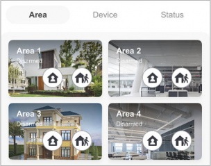
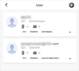
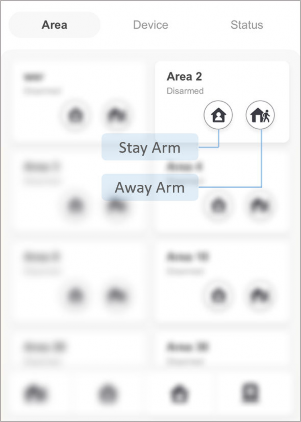
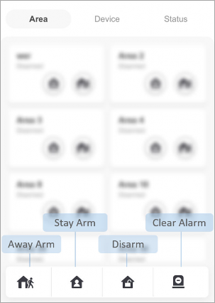
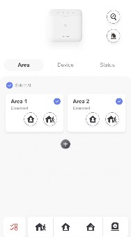

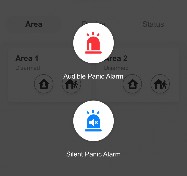
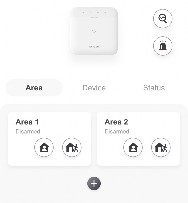
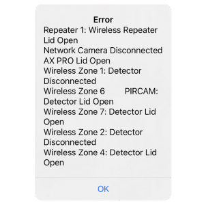


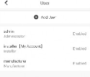
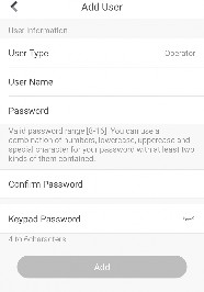


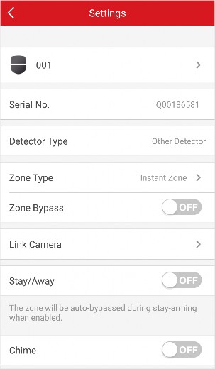
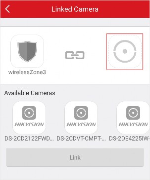

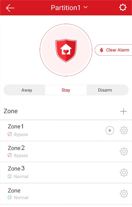

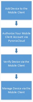
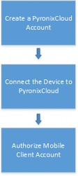
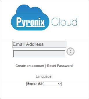
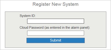
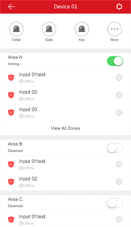

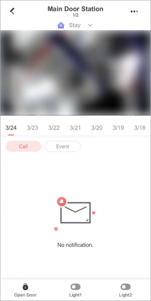
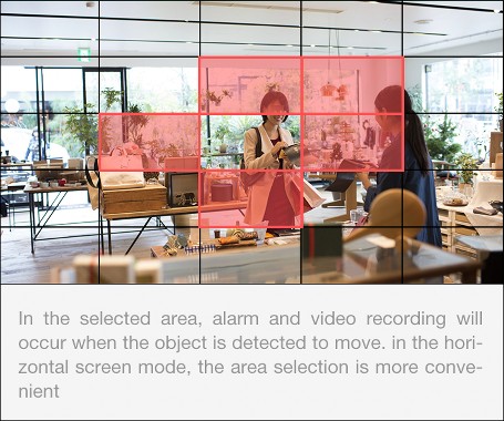
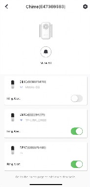
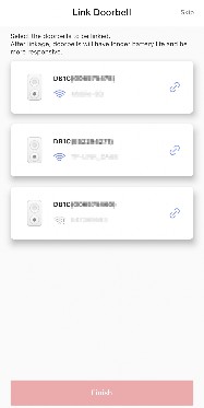
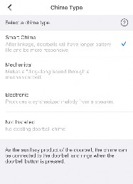
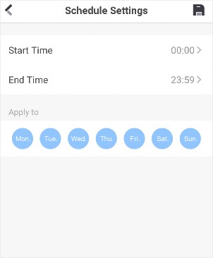

![]()
Tap More → Settings to enter the Settings page and then enable the function.
-
-
Resume Latest Live View
If you enable the function, the latest live view will be resumed each time you enter the Mobile Client. The window division mode, and the live view windows’ sequence (if in multiple-window mode) will also be restored.
Tap More → Settings to enter the Settings page, and then enable the function.
-
Display/Hide Channel-Zero
Channel-zero, known as virtual channel, can show the videos from all channels of the device, reducing the bandwidth while simultaneously previewing from multi-channel. It can acquire image information and save bandwidth for transmission through encoding and configuring output images.
Tap More → Settings and then enable the Mobile Client to display channel-zero.
-
Auto-Download Upgrade File
Note
If you enable Auto-Donwload Upgrade File, the Mobile Client will automatically download the upgrade file in Wi-Fi networks, which helps speed up the device upgrade process.
For details about upgrading device, see Upgrade Device Firmware .
Tap More → Settings to enter the Settings page and then enable the function.
-
Manage Custom Audio
-
You can record audio files for setting them as the custom audio prompts for the alarms sent from the channels linked to specific models of DVR.
Perform this task to record an audio file.
-
Tap More → Settings → Custom Audio Management .
-
Tap Start Recording to start recording, and then tap Stop Recording. The Complete Recording dialog pops up.
Note
-
Optional: Create a name for the audio file.
By default, the file name is the time (accurate to second) when recording stops.
-
Tap Confirm.
-
Optional: Perform further operations.
Rename Audio Swipe left and then tap ![]() to rename the audio file.
to rename the audio file.
Delete Audio Swipe left and then tap ![]() to delete the audio file.
to delete the audio file.
Set custom audio prompt for the alarms sent from the channels linked to specific models of DVR. For details, see Set Custom Audio .
UD27169B